
This is a continuation from part 3 (LINK)
5. Integration Builder Configuration
The configuration here consists of creating:
- Communication Scenario
- Communication Channels
- Receiver Determination
- Interface Determination
- Sender Agreement
- Receiver Agreement
5.1 Creating Communication Scenario
The configuration of the Communication Scenario is performed in the Integration Builder:

Start ‘Integration Builder’
Depending on your stings, this might start up on different views. Make sure you change this to the ‘Configuration Scenario View’ – see below:
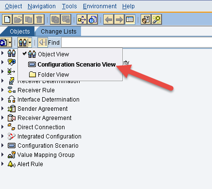
This will change the view to look like this:
You see a list of all of the already configured Communication Scenarios.
First we create a new Communication Scenario – this is the ‘container’ where we will add all the configuration needed.

Select a name for your scenario and click ‘Create’.
This will open an empty scenario:
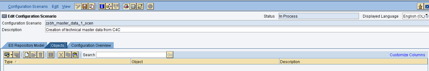
At this point, the ‘Objects’ list is empty, as we have not assigned or created and objects.
Now ‘Save’ and ‘Activate’.

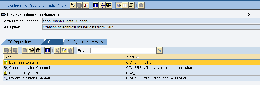
When we are done we will have the following objects:

The ‘Business Systems’ are already configured in the system (REMEMBER THAT ONE OF THE ASSUMPTIONS IS THAT WE ALREADY HAVE PI COMMUNICATING WITH ERP AND C4C).
What we will create is:
- 2 Communication Channels (one for sender and one for receiver)
- 1 Sender Agreement
- 1 Receiver Agreement
- 1 Receiver Determination
- 1 Interface Determination
For ‘Communication Channels’ we will use the following names:
- ‘zbh_tech_comm_chan_sender’ – for the sender channel
- ‘zsbh_tech_comm_receiver’ – for the receiver channel
THE OTHER COMPONENTS DOES NOT HAVE A NAME, BUT ARE ASSIGNED TO OUR COMMUNICATION SCENARIO.
5.2 Creating Communication Channels
Click on the ‘Create’ icon:


Select ‘Communication Channel’ – you will also see that the object is automatically assigned to our scenario, because we executed the ‘Create’ from within the scenario.
First select ‘Communication Component’, and then provide the name for the Communication Channel and a description:

Since this is the sender – we select
CfC_ERP_UTIL from the drop down list.
In the beginning of the document, we stated that
CfC_ERP_UTIL is the C4C system, and in our case the sender of the web service request.
The click ‘Create’.

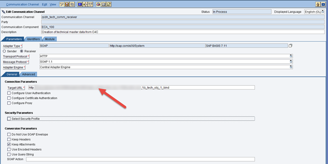
On ‘Adapter Type’ select the search and select SOAP, SAP BASIS 7.11.

Then mark ‘Use Query String’.

Then ‘Save’ and ‘Activate’.
Go back to the ‘Configuration Scenario’

Now ‘Save’ and ‘Activate’

Pay attention to that the ‘Business System’ was also added.
----
Now we create the receiver communication channel.


The communication Component for the receiver is the ERP system, in our configuration
ECA_100.
Select ‘Create’.

Like before – search for the ‘Adapter Type’ and select SOAP, SAP BASIS 7.11.

Click on ‘Receiver’ and you will see a target URL opening up. This URL is the one provided from the WSDL of our service.
One option is to find our service in SOAMANAGER (ERP).
HERE WE ARE JUMPING TO SOAMANAGER - Find our service in SOAMANAGER, then click in the icon (see arrow below):


Click on execute and a browser will open with the WSDL. Go to the end of the WSDL and copy the URL listed in the address location:

This URL you paste in to the ‘Target URL’ for the communication channel configuration:
At the end of the URL point to the right client, in our case client 100 (adding ?sap-client=100 after the URL):

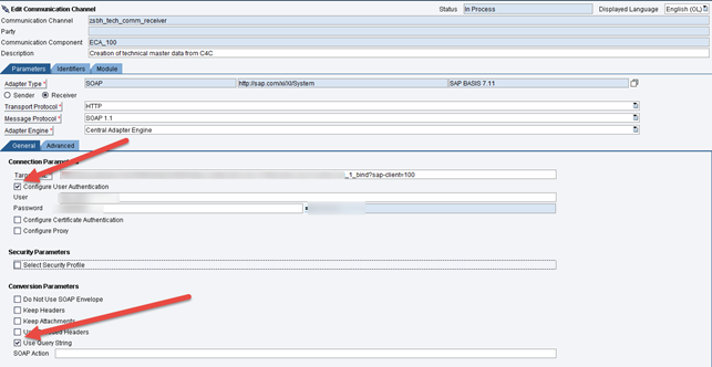
The select ‘User Authentication’. This is a user from ERP with authorization execute web service.
Also, check the ‘Use Query String’.
Now ‘Save’ and ‘Activate’.
Then go back to the Configuration Scenario and save and ‘Activate’ again.
We have now finished the configuration of both Communication Channels.
Continued in PART 5
