
- SAP Community
- Products and Technology
- Technology
- Technology Blogs by SAP
- Integration Flow Simulation in SAP Cloud Integrati...
Technology Blogs by SAP
Learn how to extend and personalize SAP applications. Follow the SAP technology blog for insights into SAP BTP, ABAP, SAP Analytics Cloud, SAP HANA, and more.
Turn on suggestions
Auto-suggest helps you quickly narrow down your search results by suggesting possible matches as you type.
Showing results for
Advisor
Options
- Subscribe to RSS Feed
- Mark as New
- Mark as Read
- Bookmark
- Subscribe
- Printer Friendly Page
- Report Inappropriate Content
04-13-2020
6:20 AM
Introduction
SAP Cloud Integration April 2020 release (3.23.x/4.11.x) provides a feature to simulate Integration Flow. This feature is described in the SAP Help Portal ( see Integration Flow Simulation).
New with SAP Cloud Integration release (3.31.x/6.7.x)
SAP Cloud Integration release (3.31.x/6.7.x) provides revamped version of integration flow editor where we have removed simulation mode. You can leverage simulation feature in both edit and read-only mode of integration flow without need of simulation mode. Revamped of integration flow editor is described in this blog
New with SAP Cloud Integration October 2020 release (3.30.x/6.6.x)
SAP Cloud Integration October 2020 release (3.30.x/6.6.x) provides an extended feature to support simulation of an integration flow with the various types of body files and simulation in the edit mode of integration flow.
You can simulate an integration flow with various types of body files. This feature is described in this blog.
Simulate an integration flow in the edit mode. This feature is explained in this blog.
New with SAP Cloud Integration August 2020 release (3.28.x/4.15.x)
With this release, IDoc and PKCS Splitter flow steps are supported in the integration flow simulation.
New with SAP Cloud Integration July 2020 release (3.27.x/4.14.x)
With this release, General Splitter, Iterating Splitter and Looping Process Call flow step is supported in the integration flow simulation. Other variant of the Splitter will be supported in the successive release.
In addition, we have simplified the feeding of the simulation message input by providing the smart upload capability.
On completion of the simulation of integration flow, the processed message can be downloaded.
Please refer the Spitter and Looping process call section for details.
New with SAP Cloud Integration June 2020 release (3.26.x/4.13.x)
With this release, Gather flow step is supported in the integration flow simulation.
New with SAP Cloud Integration May 2020 release (3.24.x/4.12.x)
With this release, Multicast flow step is supported in the integration flow simulation.
What is Integration Flow Simulation
Simulation in an Integration flow Web editor is the feature that enables integration developers to test a subset of integration flow during development without the need of deploying an integration flow and enable trace explicitly.
Why Integration Flow Simulation
As we know modelling an integration flow, deploying and enabling trace to validate all the steps of integration flow is a time-consuming task. Developing integration flow is an incremental process that needs the repetition of the cycle of deploying & enabling trace which is cumbersome and reduces developer productivity. Therefore, there is a need to have a test environment that will give an instant outcome of the integration flow and as well enables developers to negate the possibility of the deployment failure of the integration flow.
To overcome this challenge, we have now introduced an Integration Flow Simulation functionality in SAP Cloud Integration Web Editor that will help developers to validate the subset of integration flow and assess the behavioral outcome of steps in the integration flow. The simulation feature will simulate the execution of the integration flow and gives the developer the output that could be in the form of Payload, Headers & Properties.
How to use Integration Flow Simulation
In this section, we explain how to use this feature and leverage the benefits to test the integration flow. But before this, you should be well versed with the following.
- Functionalities and operations of symbols that are associated with the Simulation feature.
- Different Color convention associated with the symbols.
Functionalities of the symbols
| Functionalities | Symbolic Representation | Details |
| Simulation Mode |  | This switch enables the simulation functionality and it's located at the top-right corner in the canvas. A simulation tool will be available on the canvas once you turn ON the simulation mode. Note - Simulation mode is OFF by default. |
| Start Point |  | A Start Point is an element of Simulation. It needs to be placed where simulation to be done at first on your flow path. It feeds a simulation input. |
| End Point |  | An End Point is an element of simulation that needs to be placed to end the simulation on your connection or the defined path of simulation. |
| Add Simulation input |  | On click of start point, Add Simulation Input dialog opens. This capability allows integration developer to add input that could be as follows:
You can copy paste the payload in the body |
| Add Simulation Response |  | This capability allows integration developer to simulate the response from the receiver adapter connected to Request-Reply step. Simulate the read of variable in the content modifier. Simulate the read of the data store in the Get element. |
| Run Simulation |  | It's an action element available in the simulation tool, which is used to run the simulation once the start and end point have been defined. |
| Clear Simulation | It's an action button on the simulation tool that is used to remove all the simulation elements like start point, end point, message processing output for all the previously defined. | |
| Message Envelope |  | When the simulation run is successful, the message envelope is rendered and located between the start and end point. On Click of message envelope, message content display in the form of header, properties, and message body. |
Color conventions of symbol
| Color Code | Used For | Details |
| Blue | Start point and Message Envelope | Start Point: Always remains the same. Message Envelope: Appear after running the simulation successfully. You can proceed to check simulation output just by clicking on it. |
| Red | End point and Message Envelope | Appears when there are errors. Click on the respective functionalities to check error messages. |
| Black | End point | Normal behavior and no action required. |
| Green | End point | Appears on successful execution of simulation. |
Hope you are aware of the functionalities and color convention of the symbols, now it makes sense to take you through the process of simulating a subset and the complete integration flow.
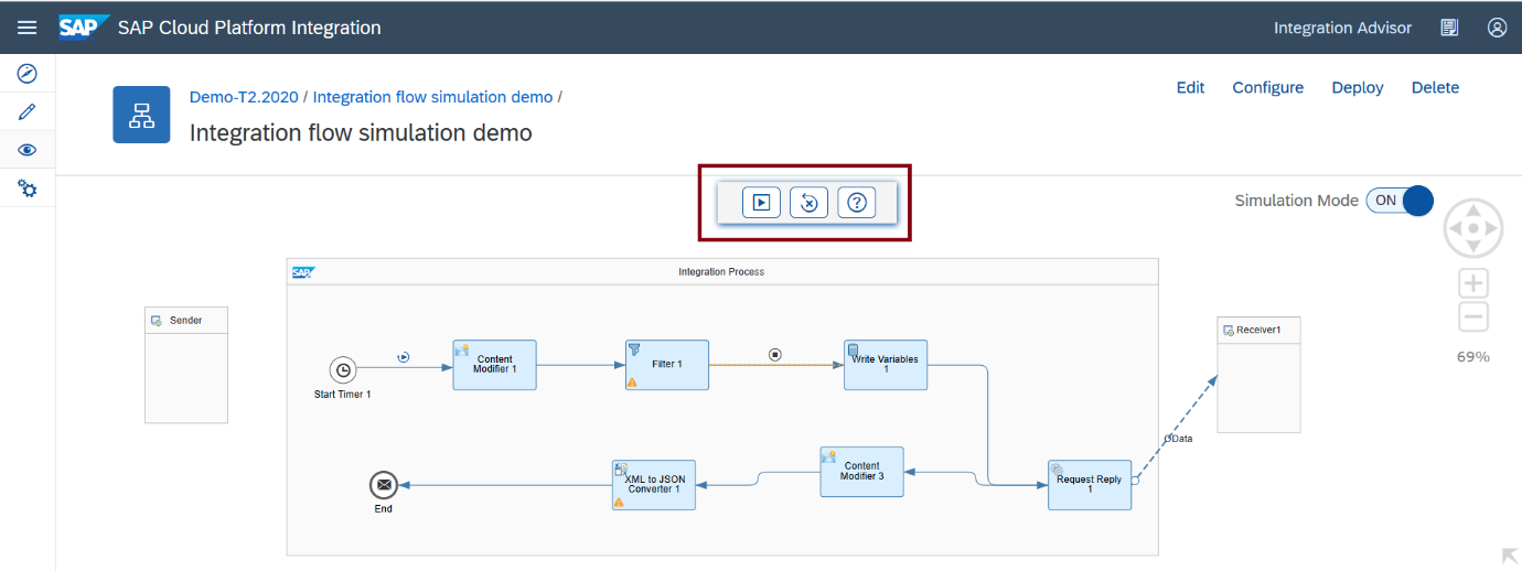
Open your integration flow in read-only mode. And on the top right corner of the integration flow editor, you see a switch button that helps you to enable the simulation tool. It is switched off by default.

On enabling the Simulation button, the simulation tool appears over the integration flow.

This tool lets you,
- Run the simulation
- Clear simulation
- Context sensitive help that will direct you to the information needed.
Let us first set the simulation for a subset of this integration flow.
Click on the connector line where you need to define the start point of your simulation.

Follow the same to define the End point for your simulation.

Now you can see that the first two icons of the simulation tool have been enabled.
Now, we need to provide an input for the simulation to run. You can add a header value or a property or you can enter a payload in the body. For this test, let us provide an input payload in the body. You must click the start point which will open the “Add Simulation Input” dialog.


For this test of an integration flow, let us provide following input payload in the body. You can copy paste the following code.
<root>

<order>

<orderno>OD0001</orderno>

</order>

</root>
The subset of an integration flow now filters the incoming payload based on the XPath provided in the Filter step.

Let us run the simulation now.

The simulation is complete and if it is successful, the End Point turns from black to green.

The message envelope is decorated between the Start and End point. On click of the Message Envelope, the processed output of the step will be shown in the property sheet.
Based on the simulation input and the XPath provided, the output message should consist of the order details.

Let us clear the simulation.

Click on the Clear Simulation from the tool. Simulation data, settings is cleared off.

Simulation of integration flow with Splitter and Looping process call

Image1 : Select start point to feed simulation input message

Image2 : Click to upload the input message from the file system
This smart upload capability allows to upload the message zip which comprises of *.headers, *.properties and *.body file. Zip file can contain any permutation and combination of the supported file. In addition to this, you can as well upload the supported file individually.

Image3 : On upload, the body, properties and headers will be populated
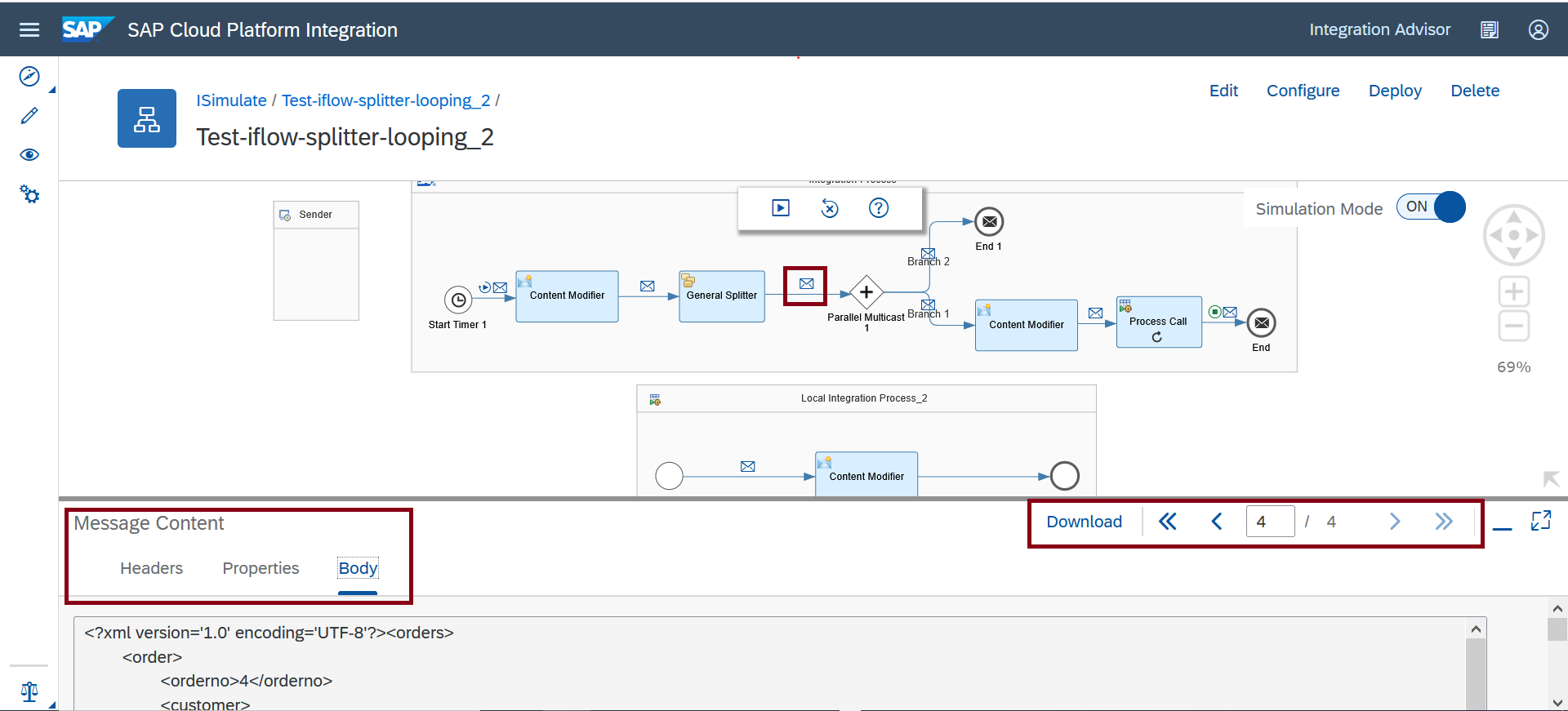
Image4 : Spitter's processed message upon the completion of integration flow simulation
Each processed message of the Splitter can be examined through the pagination control. This control has a capability to navigate to next page, previous page, last page and first page.

Image5 : Processed messages of Looping Process Call upon the completion of integration flow simulation
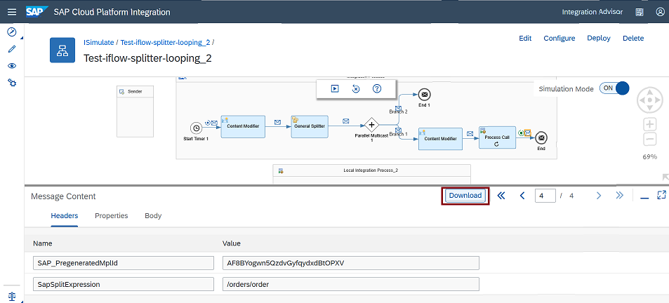
Image6 : Download processed message after the completion of simulation.

Image6 : Downloaded message will be in the zip structure which comprises of headers, properties and body
Supported Components for an Integration Flow Simulation
Details on Components Supported in the Simulation Process.
| Category | Elements | Supportability |
| Message Transformers |
| All. Note - For the Script flow step HTTP calls can’t be simulated. |
| Call |
| All |
| Message Routing |
| All Routing Elements except the following: -
Note: It will be available in the subsequent releases. |
| Security Elements |
| All. |
| Persistence |
| All. You can only simulate the read of variable value and data store. |
| Validator | XML Validator | All. |
Benefits of Simulation
This section lists the benefits of simulation in an integration flow.
- Simulate the subset of integration flow without need to deploy and enable tracing.
- This feature offers realistic input to integration developers when designing an integration flow.
- Simulation allows the developer to simulate dependencies and identify issues at the early stage.
- It helps integration developer to identify the probable deployment errors.
- Any errors identified during the simulation, records as a message along with recommendations to fix it.
- Improves the integration developer productivity.
Scope of an Integration Flow Simulation
With the first release (3.23.x/4.11.x) of the Integration flow simulation, we would support the simulation of an integration flow in the read-only mode of integration flow web editor.
The maximum no of steps which can participate in the simulation of integration flow is 10.
Maximum size of the payload – 1 MB
Successive Increments of an Integration Flow Simulation
The successive increments in the integration flow simulation will bring some more additional capabilities. Some of the salient features are as follows:
- Start supporting the remaining components which are not supported.
- Some more improvements in the validation handling scenarios.
- Simulating steps in the edit mode of integration flow.
- Persistency/Save of simulated data, configuration and settings.
I hope, you can benefit from the enhancements presented in this blog post. I've shared a video which captures more scenarios related to Integration Flow Simulation.
Integration Flow Simulation Video
In case of questions or feedback, please feel free to comment on this blog.
- SAP Managed Tags:
- Cloud Integration
Labels:
32 Comments
You must be a registered user to add a comment. If you've already registered, sign in. Otherwise, register and sign in.
Labels in this area
-
ABAP CDS Views - CDC (Change Data Capture)
2 -
AI
1 -
Analyze Workload Data
1 -
BTP
1 -
Business and IT Integration
2 -
Business application stu
1 -
Business Technology Platform
1 -
Business Trends
1,661 -
Business Trends
88 -
CAP
1 -
cf
1 -
Cloud Foundry
1 -
Confluent
1 -
Customer COE Basics and Fundamentals
1 -
Customer COE Latest and Greatest
3 -
Customer Data Browser app
1 -
Data Analysis Tool
1 -
data migration
1 -
data transfer
1 -
Datasphere
2 -
Event Information
1,400 -
Event Information
65 -
Expert
1 -
Expert Insights
178 -
Expert Insights
280 -
General
1 -
Google cloud
1 -
Google Next'24
1 -
Kafka
1 -
Life at SAP
784 -
Life at SAP
11 -
Migrate your Data App
1 -
MTA
1 -
Network Performance Analysis
1 -
NodeJS
1 -
PDF
1 -
POC
1 -
Product Updates
4,577 -
Product Updates
330 -
Replication Flow
1 -
RisewithSAP
1 -
SAP BTP
1 -
SAP BTP Cloud Foundry
1 -
SAP Cloud ALM
1 -
SAP Cloud Application Programming Model
1 -
SAP Datasphere
2 -
SAP S4HANA Cloud
1 -
SAP S4HANA Migration Cockpit
1 -
Technology Updates
6,886 -
Technology Updates
407 -
Workload Fluctuations
1
Related Content
- Hack2Build on Business AI – Highlighted Use Cases in Technology Blogs by SAP
- SAP Partners unleash Business AI potential at global Hack2Build in Technology Blogs by SAP
- It’s Official - SAP BTP is Again a Leader in G2’s Reports in Technology Blogs by SAP
- Magic Numbers : A Solution to Foreign Characters in SAP CPI in Technology Blogs by Members
- Convert multiple xml's into single Xlsx(MS Excel) using groovy script in Technology Blogs by Members
Top kudoed authors
| User | Count |
|---|---|
| 13 | |
| 10 | |
| 9 | |
| 7 | |
| 6 | |
| 5 | |
| 5 | |
| 5 | |
| 5 | |
| 4 |