
- SAP Community
- Groups
- Interest Groups
- Application Development
- Blog Posts
- ABAP Ray Tracer - Part 3 - The Skeleton
Application Development Blog Posts
Learn and share on deeper, cross technology development topics such as integration and connectivity, automation, cloud extensibility, developing at scale, and security.
Turn on suggestions
Auto-suggest helps you quickly narrow down your search results by suggesting possible matches as you type.
Showing results for
jamesmorrison
Active Participant
Options
- Subscribe to RSS Feed
- Mark as New
- Mark as Read
- Bookmark
- Subscribe
- Printer Friendly Page
- Report Inappropriate Content
09-24-2017
4:02 PM
Recap
I am writing a ray tracer with ABAP by studying the book "Ray Tracing from the Ground Up".
A ray tracer is able to create computer generated imagery.
If you like to know more about my motivation behind this endeavour, check out my first blog.
In my second blog I converted the first C++ classes to ABAP, which are needed to patch together my first ray tracer. On the way of conversion I managed to tackle some language feature shortcomings of ABAP, for example overloading.
Objectives
In this third blog I am going to get the most rudimentary ray tracer running. The book calls that the skeleton ray tracer.
I'm gonna explain the basic concept behind a ray tracer and give you code examples from my implementation to highlight this concept.
Also I let you take part how I struggled with getting my rendered results displayed.
The Skeleton Ray Tracer
The following figure gives you an idea of how ray casting works.
 |
Henrik, (2008). Ray trace diagram. [online image] Available at: Wikipedia [Accessed 22. Sep. 2017]
At this stage, my ray tracer will not be able to handle lights, shadows and cameras, these are features for the coming chapters.
After this blog I'll be able to render a single object from the position of a window, here titled as "Image".
Pull down
So how does a ray tracer work? The book boils it down to:
1. Define some objects

2. Specify a material for each object

3. Define some light sources

4. Define a window whose surface is covered with pixels


5. For each pixel

6.   Shoot a ray towards the objects from the center of the pixel

7.   Compute the nearest hit point of the ray with the objects (if any)


8.   If the ray hits an object

9.     Use the object's material and lights to compute the pixel color

     Else

10.    Set the pixel color to black
(Kevin Suffern, 2007, p. 46)
I am not implementing 2., 3., so I skip these and radically simplify 9.
1. Define some objects
Get me a world and build things upon it!
REPORT zart_main.

...

FORM render.

  DATA(world) = NEW zcl_art_world( ).

  world->build( ).

  ...

ENDFORM.My world consists of a single sphere. Spectacular!
CLASS zcl_art_world IMPLEMENTATION.

  ...

  METHOD build.

    build_single_sphere( ).

  ENDMETHOD.


  METHOD build_single_sphere.

    ...

    me->sphere->set_center_by_value( '0.0' ).

    me->sphere->set_radius( '85.0' ).

ENDMETHOD.4. Define a window whose surface is covered with pixels
I'm gonna look into the world by defining a window of 200 by 200 pixels.
Each pixel has a height and width of 1 unit.
Note: A pixel is not a dot, it's a square in space. Its area is defined by
pixel_size * pixel_size.CLASS zcl_art_world IMPLEMENTATION.
METHOD build_single_sphere.
me->viewplane->set_hres( 200 ).
me->viewplane->set_vres( 200 ).
me->viewplane->set_pixel_size( '1.0' ).
me->viewplane->set_gamma( '1.0' ).
...
ENDMETHOD.5. For each pixel
The following code triggers the whole rendering process.
REPORT zart_main.

...

FORM render.

  ...

  world->render_scene( ).

  ...

ENDFORM.Now trigger the calculation row by row.
CLASS zcl_art_world DEFINITION.

  METHOD render_scene.

    ...

    DATA row TYPE int4.

    DATA column TYPE int4.

    WHILE row < vres.

      column = 0.

      WHILE column < hres.

        ...

        ADD 1 TO column.

      ENDWHILE.


      ADD 1 TO row.

    ENDWHILE.

ENDMETHOD.6. Shoot a ray towards the objects from the center of the pixel
Build me a ray, which is facing towards the sphere (
i_z = -1) and originate the ray 100 units away from the world origin, from the center of each pixel.CLASS zcl_art_world DEFINITION.
METHOD render_scene.
...
"Loop
DATA(ray) = zcl_art_ray=>new_default( ).
ray->direction = zcl_art_vector3d=>new_individual(
i_x = 0
i_y = 0
i_z = -1 ).
ray->origin = zcl_art_point3d=>new_individual(
i_x = pixel_size * ( column - hres / '2.0' + '0.5' )
i_y = pixel_size * ( row - vres / '2.0' + '0.5' )
i_z = '100.0' ).
DATA(pixel_color) = tracer->trace_ray( ray ).
"Loop End
...
ENDMETHOD.7. Compute the nearest hit point of the ray with the objects (if any)
t and shade_rec aren't used in this version of the ray tracer, but it will be in future versions.Right now all I care about is, whether the ray hits the sphere (
DATA(hit)).CLASS zcl_art_single_sphere IMPLEMENTATION.
METHOD trace_ray.
DATA t TYPE decfloat16.
DATA(shade_rec) = zcl_art_shade_rec=>new_from_world( _world ).
_world->sphere->hit(
EXPORTING
i_ray = i_ray
IMPORTING
e_tmin = t
e_hit = DATA(hit)
CHANGING
c_shade_rec = shade_rec ).
...
ENDMETHOD.8. If the ray hits ...
...an object

  Use the object's material and the lights to compute the pixel color

Else

  Set the pixel color to black
If the ray hits the sphere, I'm gonna taint the pixel red, or otherwise black.
CLASS zcl_art_single_sphere IMPLEMENTATION.

  METHOD trace_ray.

    ...

    IF hit = abap_true.

      r_result = zcl_art_rgb_color=>new_copy( zcl_art_rgb_color=>red ).

    ELSE.

      r_result = zcl_art_rgb_color=>new_copy( zcl_art_rgb_color=>black ).

    ENDIF.
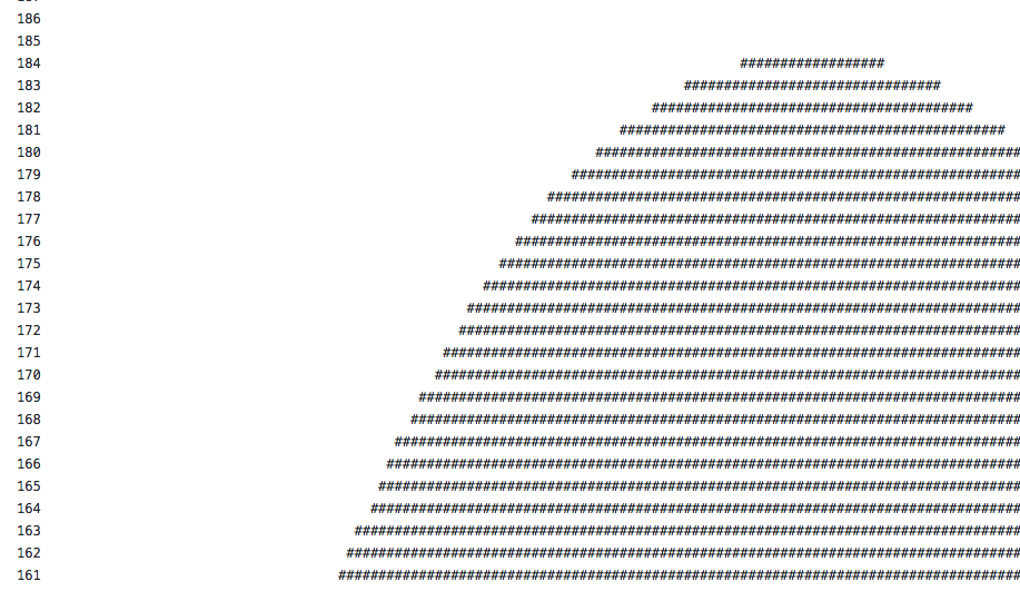
ENDMETHOD.First Attempt: #-Character
At this point, I am getting a pixel color, but how the heck am I going to display that?
A quick google search revealed that this might be more difficult than I expected.
For verifying if my code is worth something, I turned to the good old character approach.
Whenever I am hitting the sphere, I'm gonna write a #-character at the row/column position.
CLASS zcl_art_world IMPLEMENTATION.

  METHOD display_pixel.

    ...


    "Write the row counter in front of each line

    IF x = 0.

      WRITE /1(*) y NO-GAP.

    ENDIF.


    "Write a #-character at the column position,

    "if the pixel isn't black

    IF r > 0 OR g > 0 OR b > 0.

      WRITE AT x(1) '#'.

    ENDIF.

ENDMETHOD.And then it revealed itself ...
 |
... as an egg. 🙂
 |
Second Attempt: Pixel
Alright, my code seems to work. But I really need to be able to display pixels with a certain RGB color value.
I didn't find anything which let me place at
x and y coordinates a pixel with a certain color.After reading an old blog, my gut feeling told me that this is going to need extra effort on my end.
thomas.jung provided a solution to the authors question, which put me in the right direction.
Though I still was looking for an easy way out, which made me tackle that problem from two sides.
I asked the community, if someone still has Thomas Jungs full fledged Bitmap image processing class laying around, which he posted in response to helping that fellow from above. I was hoping to just copy & paste the bitmap part I need and be done with it.
And while the community was digging in their SAP graveyards, searching for a 10 years old class, I was reading up on how to:
- create a bitmap
- display a bitmap
As Thomas mentioned, Wikipedia has an excellent article regarding the Bitmap file format, dissecting all the parts, like how a bitmap header is structured. That allowed me to come up with my own abstraction.
CLASS zcl_art_bitmap DEFINITION

  PUBLIC

  FINAL

  CREATE PUBLIC.


  PUBLIC SECTION.

    TYPES:

      BEGIN OF pixel,

        x TYPE int4,

        y TYPE int4,

        r TYPE int4,

        g TYPE int4,

        b TYPE int4,

      END OF pixel.


    METHODS:

      constructor

        IMPORTING

          i_image_height_in_pixel TYPE int4

          i_image_width_in_pixel  TYPE int4,


      add_pixel

        IMPORTING

          i_pixel TYPE pixel,


      build

        RETURNING

          VALUE(r_bitmap) TYPE xstring.

...


CLASS zcl_art_bitmap IMPLEMENTATION.

  METHOD add_pixel.

    DATA:

      r TYPE x LENGTH 1,

      g TYPE x LENGTH 1,

      b TYPE x LENGTH 1.


    _converter->convert( EXPORTING data = i_pixel-r IMPORTING buffer = r ).

    _converter->convert( EXPORTING data = i_pixel-g IMPORTING buffer = g ).

    _converter->convert( EXPORTING data = i_pixel-b IMPORTING buffer = b ).


    CONCATENATE _data b g r INTO _data IN BYTE MODE.


    IF i_pixel-x + 1 = _image_width_in_pixel.

      CONCATENATE _data _remaining_bytes INTO _data IN BYTE MODE.

    ENDIF.

  ENDMETHOD.


  METHOD build_header.

    DATA magic_number TYPE x LENGTH 2.

    _converter->convert( EXPORTING data = _co_magic_number_in_ascii IMPORTING buffer = magic_number ).


    DATA file_size TYPE x LENGTH 4.

    DATA(bmp_file_size_in_byte) = get_bmp_file_size( ).

    _converter->convert( EXPORTING data = bmp_file_size_in_byte IMPORTING buffer = file_size ).


    ...


    CONCATENATE magic_number

                file_size

                _co_application_specific

                _co_application_specific

                offset

                dib_header_size

                image_width

                image_height

                num_color_palates

                bits_per_pixel

                _co_bi_rgb_compression

                raw_bitmap_size

                print_resolution

                print_resolution

                _co_num_colors_in_palettes

                _co_important_colors

                INTO _header IN BYTE MODE.

  ENDMETHOD.

...After reading several articles (1, 2, 3 and 4) on how to display bitmaps with Dynpro, I was also able to conjure something, which got the job done in the display department.
REPORT zart_main.

...

FORM display USING i_bitmap type xstring.

  "now we go from XSTRING back to binary characters

  TYPES binary_row TYPE x LENGTH 256.

  DATA binary_rows TYPE TABLE OF binary_row WITH DEFAULT KEY.


  CALL FUNCTION 'SCMS_XSTRING_TO_BINARY'

    EXPORTING

      buffer     = i_bitmap

    TABLES

      binary_tab = binary_rows.


  "and now we prepare everything for display

  DATA url TYPE cndp_url.

  CALL FUNCTION 'DP_CREATE_URL'

    EXPORTING

      type    = 'IMAGE'

      subtype = 'BMP'

    TABLES

      data    = binary_rows

    CHANGING

      url     = url.


  DATA(container) = NEW cl_gui_custom_container( container_name = 'PICTURE' ).

  DATA(picture) = NEW cl_gui_picture( parent = container ).

  picture->load_picture_from_url( url ).

  picture->set_display_mode( picture->display_mode_normal ).

ENDFORM.Et voilá... My first rendered image.

That was quite a moment for me ... at 2:45 AM ... ?
Conclusion
I wrote the glue code to orchestrate the necessary classes, which are involved in ray tracing an image.
Also, I managed to display pixel color values on a classical Dynpro screen, with the help of my own bitmap file format abstraction class (
ZCL_ART_BITMAP).The fundamentals of my ray tracer are working.
I am now able to start adding features to my ray tracer.
What's Next
One sphere is boring. I want more objects, and more objects I'm gonna give you.
The next thing on the menu is to render multiple objects, aka more spheres and more planes at the same time.
Also I'm gonna explain a bit about converting method parameter signatures between C++ and ABAP.
Thanks,
André
- SAP Managed Tags:
- ABAP Development
You must be a registered user to add a comment. If you've already registered, sign in. Otherwise, register and sign in.
Labels in this area
-
A Dynamic Memory Allocation Tool
1 -
ABAP
8 -
abap cds
1 -
ABAP CDS Views
14 -
ABAP class
1 -
ABAP Cloud
1 -
ABAP Development
4 -
ABAP in Eclipse
1 -
ABAP Keyword Documentation
2 -
ABAP OOABAP
2 -
ABAP Programming
1 -
abap technical
1 -
ABAP test cockpit
7 -
ABAP test cokpit
1 -
ADT
1 -
Advanced Event Mesh
1 -
AEM
1 -
AI
1 -
API and Integration
1 -
APIs
8 -
APIs ABAP
1 -
App Dev and Integration
1 -
Application Development
2 -
application job
1 -
archivelinks
1 -
Automation
4 -
BTP
1 -
CAP
1 -
CAPM
1 -
Career Development
3 -
CL_GUI_FRONTEND_SERVICES
1 -
CL_SALV_TABLE
1 -
Cloud Extensibility
8 -
Cloud Native
7 -
Cloud Platform Integration
1 -
CloudEvents
2 -
CMIS
1 -
Connection
1 -
container
1 -
Debugging
2 -
Developer extensibility
1 -
Developing at Scale
4 -
DMS
1 -
dynamic logpoints
1 -
Eclipse ADT ABAP Development Tools
1 -
EDA
1 -
Event Mesh
1 -
Expert
1 -
Field Symbols in ABAP
1 -
Fiori
1 -
Fiori App Extension
1 -
Forms & Templates
1 -
IBM watsonx
1 -
Integration & Connectivity
10 -
JavaScripts used by Adobe Forms
1 -
joule
1 -
NodeJS
1 -
ODATA
3 -
OOABAP
3 -
Outbound queue
1 -
Product Updates
1 -
Programming Models
13 -
RFC
1 -
RFFOEDI1
1 -
SAP BAS
1 -
SAP BTP
1 -
SAP Build
1 -
SAP Build apps
1 -
SAP Build CodeJam
1 -
SAP CodeTalk
1 -
SAP Odata
1 -
SAP UI5
1 -
SAP UI5 Custom Library
1 -
SAPEnhancements
1 -
SapMachine
1 -
security
3 -
text editor
1 -
Tools
16 -
User Experience
5
Top kudoed authors
| User | Count |
|---|---|
| 6 | |
| 5 | |
| 3 | |
| 3 | |
| 2 | |
| 2 | |
| 2 | |
| 1 | |
| 1 | |
| 1 |