
- SAP Community
- Products and Technology
- Technology
- Technology Blogs by SAP
- Your First Extension: Part 9a - Drawing an Indicat...
Technology Blogs by SAP
Learn how to extend and personalize SAP applications. Follow the SAP technology blog for insights into SAP BTP, ABAP, SAP Analytics Cloud, SAP HANA, and more.
Turn on suggestions
Auto-suggest helps you quickly narrow down your search results by suggesting possible matches as you type.
Showing results for
Advisor
Options
- Subscribe to RSS Feed
- Mark as New
- Mark as Read
- Bookmark
- Subscribe
- Printer Friendly Page
- Report Inappropriate Content
02-22-2016
3:56 PM
This is part of a tutorial series on creating extension components for Design Studio.
Now were ready to add an indicator needle. In this installment, we'll return to our html sandbox and define our needle. Next time, we'll migrate the changes into a component. It will be a pointer, like you'd find in an analog car speedometer. There are a few ways that we could add the needle:
- We add an image and rotate it. Either the developer would use a fixed image, or the designer would take an arbitrary image, define a centerpoint and use that. The problem with raster images is that they can't scale properly with the rest of the component.
- We add an SVG shape and rotate it. This would work and we could then have the user specify an external SVG file, but dynamically modifying it afterwards is also very difficult. Also editor to component workflows are not guaranteed to be simple.
- We simply draw a fixed style of pointer in the component, using D3. This is the least flexible way of doing it, but the simplest from a development ,designer usability and workflow perspective. We'll choose this route and leave the file reference version as an exercise.
Needle Layout
We've already covered the tools needed to build our needle. It will consist of two SVG paths: an arc and a coordinate based path. We learned how to draw way back in Part 2a and have used that technique a few times since then. We first learned to draw paths when we designed our padding visualizer in Part 4a and have also used this tenchnique since. The path will be used to draw the needle and the arc will be used to draw the "base pin"; for those cases when the designer wants to put a circle at the axis of the needle, like you'd find in an analog automobile speedometer. The pin - if present - will be drawn over the needle. We'll use four coordinates to draw the needle. The designer will have a few properties, with which she can specify the shape of the needle and base pin.
- Needle Width: The width of the needle, in relative terms (as a %) to the size of the gauge. So if it is set to 20%, then the needle's width will be 20% of whatever the radius of the gauge is; allowing it to scale.
- Needle Tail Length: As a % of the gauge radius. If this is positive, then the needle will be diamond shaped. It could also be negative or zero (or not there at all).
- Needle Length: As a % of the gauge radius. Again, this could theoretically be zero or even negative (and point in the opposite direction), though I'm not sure what use case would call for this.
- Diameter of the Base Pin: As a % of the gauge radius. Using radius would be consistent with the format of the overall gauge, but we chose to define the width to be consistent with the width of the needle. If the designer sets this to the same value as she set the needle width to, they will be the same size.
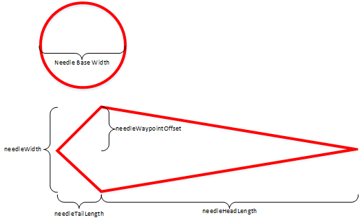
We can easily define the waypoints for the needle's brush strokes:
| X | Y |
|---|---|
| 0 | needleHeadLength |
| needleWaypointOffset* | 0 |
| 0 | -(needleTailLength) |
| -(needleWaypointOffset*) | 0 |
| 0 | needleHeadLength |
*needleWaypointOffset is a calculated property, needleWidth/2.
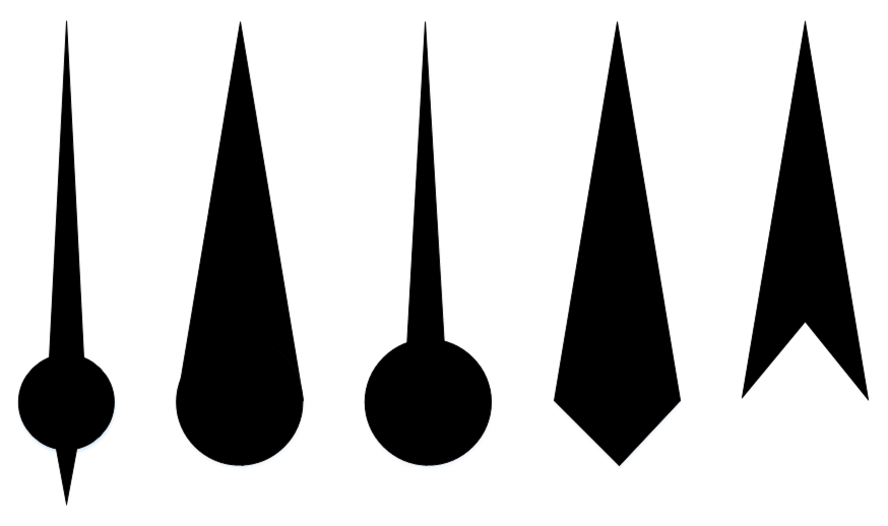
By combining these properties, brush stroke width and whether or not the shapes are filled, we can create a plethora of needle variants, with just a handful of properties. Below is just a sample of what is possible.
In order to do this, we'll follow the workflow below and keep a few things in mind.
- The needle might not be drawn at all. It should be optional.
- If the needle is drawn, the base pin might or might not be drawn. It should also be optional.
- We'll need to apply a rotational transformation to the needle stroke waypoints, before drawing them.
- Recall that to draw the stroke path, we're going to need an "accessor function" in the "d" property of the path.
- When/If we draw the base pin, we'll define the inner and outer radii based on whetrher or not we want to fill the pin. If we don"t want to fill it, then the inner and outer radii need to line up with the inside and outside of the needle brushe strokes respectively. If we do fill it in, then our inner radius will be zero.
- If we don't fill in the base pin, then we'll need to have the option of not drawing the tail, or filling the needle in. This way won't have the lines from the tail when we don't need or want them.
- If we're not filling in the needle or base pin, then we'll want the option to only draw the "back" side of the pin arc: a semi-circle. This combination can give us a wireframe version of the needle second from the left, above.
- All lines and fills will be a single color, for the sake of simplicity.

We've now laid out the logic workflow. Since we're not breaking new ground in terms of technique, we'll simply post the sandbox html file. The needle and base pin as created between lines 120 and 230. Next time, we'll refactor this new code into a component.
<!DOCTYPE html>
<html>
<head>
<meta http-equiv='X-UA-Compatible' content='IE=edge' />
<title>Part 5</title>
<div id='content'></div>
<script src="https://cdnjs.cloudflare.com/ajax/libs/d3/3.5.6/d3.min.js" charset="utf-8"></script>
<!-- <script src="file://d3/d3.js" charset="utf-8"></script>-->
<script>
var vis = d3.select("#content").append("svg:svg").attr("width", "100%").attr("height", "100%");
var pi = Math.PI;
//Viz definitiions
var innerRad = 0;
//var outerRad = 70;
var width = 200;
var height = 200;
var startAngleDeg = -45;
var endAngleDeg = 45;
var colorCode = "red";
//Outer Dimensions & Positioning
var paddingTop = 10;
var paddingBottom = 10;
var paddingLeft = 10;
var paddingRight = 10;
//The total size of the component is calculated from its parts
// Find the larger left/right padding
var lrPadding = paddingLeft + paddingRight;
var tbPadding = paddingTop + paddingBottom;
var maxPadding = lrPadding;
if (maxPadding < tbPadding){
maxPadding = tbPadding
}
var outerRad = (width - 2*(maxPadding))/2;
//var width = (outerRad * 2) + paddingLeft + paddingRight;
//var height = (outerRad * 2) + paddingTop + paddingBottom;
//The offset will determine where the center of the arc shall be
var offsetLeft = outerRad + paddingLeft;
var offsetDown = outerRad + paddingTop;
//Don't let the arc have a negative length
if (endAngleDeg < startAngleDeg){
endAngleDeg = startAngleDeg;
alert("End angle may not be less than start angle!");
}
var arcDef = d3.svg.arc()
.innerRadius(innerRad)
.outerRadius(outerRad)
.startAngle(startAngleDeg * (pi/180)) //converting from degs to radians
.endAngle(endAngleDeg * (pi/180)); //converting from degs to radians
var guageArc = vis.append("path")
.style("fill", colorCode)
.attr("width", width).attr("height", height) // Added height and width so arc is visible
.attr("transform", "translate(" + offsetLeft + "," + offsetDown + ")")
.attr("d", arcDef);
///////////////////////////////////////////
//Lets build a border ring around the gauge
///////////////////////////////////////////
//var visRing = d3.select("#content").append("svg:svg").attr("width", "100%").attr("height", "100%");
var ringThickness = 2;
var ringOuterRad = outerRad + ringThickness; //Outer ring starts at the outer radius of the inner arc
var ringColorCode = "black";
var ringStartAngleDeg = 0;
var ringEndAngleDeg = 360;
//Don't let the arc have a negative length
if (ringEndAngleDeg < ringStartAngleDeg){
ringEndAngleDeg = ringStartAngleDeg;
alert("End angle of outer ring may not be less than start angle!");
}
var ringArcDefinition = d3.svg.arc()
.innerRadius(outerRad)
.outerRadius(ringOuterRad)
.startAngle(ringStartAngleDeg * (pi/180)) //converting from degs to radians
.endAngle(ringEndAngleDeg * (pi/180)) //converting from degs to radians
var ringArc = vis
.append("path")
.attr("d", ringArcDefinition)
.attr("fill", ringColorCode)
.attr("transform", "translate(" + offsetLeft + "," + offsetDown + ")");
///////////////////////////////////////////
//Lets build a the start and end lines
///////////////////////////////////////////
var bracketThickness = 2;
var lineData = [endPoints (outerRad, startAngleDeg), {x:offsetLeft, y:offsetDown}, endPoints (outerRad, endAngleDeg)];
var visStartBracket = d3.select("#content").append("svg:svg").attr("width", "100%").attr("height", "100%");
var lineFunction = d3.svg.line()
.x(function(d) { return d.x; })
.y(function(d) { return d.y; })
.interpolate("linear");
var borderLines = vis
.attr("width", width).attr("height", height) // Added height and width so line is visible
.append("path")
.attr("d", lineFunction(lineData))
.attr("stroke", ringColorCode)
.attr("stroke-width", bracketThickness)
.attr("fill", "none");
//Helper function
function endPoints (lineLength, lineAngle){
var endX = offsetLeft - (lineLength * Math.sin(lineAngle * (pi/180)));
var endY = offsetDown - (lineLength * Math.cos(lineAngle * (pi/180)));
return {x:endX, y:endY}
}
///////////////////////////////////////////
//Lets add the indicator needle
///////////////////////////////////////////
var needleColorCode = "black";
var enableIndicatorNeedle = true;
var enableIndicatorNeedleTail = true;
var needleWidth = 20;
var needleHeadLength = 100;
var needleTailLength = 0;
var needleLineThickness = 2;
var fillNeedle = true;
if (enableIndicatorNeedle == true){
var needleWaypointOffset = needleWidth/2;
//needleWaypoints is defined with positive y axis being up
//The initial definition of needleWaypoints is for a full diamond, but if enableIndicatorNeedleTail is false, we'll abbreviate to a chevron
var needleWaypoints = [{x: 0,y: needleHeadLength}, {x: needleWaypointOffset,y: 0}, {x: 0,y: (-1*needleTailLength)}, {x: (-1*needleWaypointOffset),y: 0}, {x: 0,y: needleHeadLength}]
if (enableIndicatorNeedleTail == false){
if (fillNeedle == false){
//If we have no tail and no fill then there is no need to close the shape.
//Leave it as an open chevron
needleWaypoints = [{x: needleWaypointOffset,y: 0}, {x: 0,y: needleHeadLength}, {x: (-1*needleWaypointOffset),y: 0}];
}
else {
//There is no tail, but we are filling the needle.
//In this case, draw it as a triangle
needleWaypoints = [{x: 0,y: needleHeadLength}, {x: needleWaypointOffset,y: 0}, {x: (-1*needleWaypointOffset),y: 0}, {x: 0,y: needleHeadLength}]
}
}
//we need to invert the y-axis and scale the indicator to the gauge.
// If Y = 100, then that is 100% of outer radius. So of Y = 100 and outerRad = 70, then the scaled Y will be 70.
var needleFunction = d3.svg.line()
.x(function(d) { return (d.x)*(outerRad/100); })
.y(function(d) { return -1*(d.y)*(outerRad/100); })
.interpolate("linear");
//Draw the needle, either filling it in, or not
var needleFillColorCode = needleColorCode;
if (fillNeedle == false){
needleFillColorCode = "none";
}
//Draw the needle
var needle = vis
.append("g")
.attr("transform", "translate(" + offsetLeft + "," + offsetDown + ")")
.append("path")
.attr("class", "tri")
.attr("d", needleFunction(needleWaypoints))
.attr("stroke", needleColorCode)
.attr("stroke-width", needleLineThickness)
.attr("fill", needleFillColorCode);
//Arcs are in radians, but rotation transformations are in degrees. Kudos to D3 for consistency
needle.attr("transform", "rotate(" + endAngleDeg + ")");
}
///////////////////////////////////////////
//Lets add a needle base pin
///////////////////////////////////////////
var enableIndicatorNeedleBase = true;
var fullBasePinRing = true;
var fillNeedlaBasePin = true;
var needleBaseDiameter = 20;
if (enableIndicatorNeedleBase == true){
// Like the rest of the needle, the size of the pin is defined relative to the main arc, as a % value
var needleIBasennerRadius = (needleBaseDiameter/2)*(outerRad/100) - (needleLineThickness/2);
var needleBaseOuterRadius = needleIBasennerRadius + needleLineThickness;
if (fillNeedlaBasePin == true){
needleIBasennerRadius = 0.0;
}
// The pin will either be a 180 degree arc, or a 360 degree ring; starting from the 9 O'clock position.
var needleBaseStartAngle = 90.0;
var needleBaseEndAngle = 270.0;
if (fullBasePinRing == true){
needleBaseEndAngle = 450.0;
}
//Don't let the arc have a negative length
if (needleBaseEndAngle < needleBaseStartAngle){
needleBaseEndAngle = needleBaseStartAngle;
alert("End angle of outer ring may not be less than start angle!");
}
//Transform the pin ring
var nbTransformedStartAngle = needleBaseStartAngle + endAngleDeg;
var nbTransformedEndAngle = needleBaseEndAngle + endAngleDeg;
var pinArcDefinition = d3.svg.arc()
.innerRadius(needleIBasennerRadius)
.outerRadius(needleBaseOuterRadius)
.startAngle(nbTransformedStartAngle * (pi/180)) //converting from degs to radians
.endAngle(nbTransformedEndAngle * (pi/180)) //converting from degs to radians
var pinArc = vis
.append("path")
.attr("d", pinArcDefinition)
.attr("fill", needleColorCode)
.attr("transform", "translate(" + offsetLeft + "," + offsetDown + ")");
}
</script>
</head>
<body class='sapUiBody'>
<div id='content'></div>
</body>
</html>
- SAP Managed Tags:
- SAP BusinessObjects Design Studio
You must be a registered user to add a comment. If you've already registered, sign in. Otherwise, register and sign in.
Labels in this area
-
ABAP CDS Views - CDC (Change Data Capture)
2 -
AI
1 -
Analyze Workload Data
1 -
BTP
1 -
Business and IT Integration
2 -
Business application stu
1 -
Business Technology Platform
1 -
Business Trends
1,658 -
Business Trends
91 -
CAP
1 -
cf
1 -
Cloud Foundry
1 -
Confluent
1 -
Customer COE Basics and Fundamentals
1 -
Customer COE Latest and Greatest
3 -
Customer Data Browser app
1 -
Data Analysis Tool
1 -
data migration
1 -
data transfer
1 -
Datasphere
2 -
Event Information
1,400 -
Event Information
66 -
Expert
1 -
Expert Insights
177 -
Expert Insights
293 -
General
1 -
Google cloud
1 -
Google Next'24
1 -
Kafka
1 -
Life at SAP
780 -
Life at SAP
13 -
Migrate your Data App
1 -
MTA
1 -
Network Performance Analysis
1 -
NodeJS
1 -
PDF
1 -
POC
1 -
Product Updates
4,577 -
Product Updates
341 -
Replication Flow
1 -
RisewithSAP
1 -
SAP BTP
1 -
SAP BTP Cloud Foundry
1 -
SAP Cloud ALM
1 -
SAP Cloud Application Programming Model
1 -
SAP Datasphere
2 -
SAP S4HANA Cloud
1 -
SAP S4HANA Migration Cockpit
1 -
Technology Updates
6,873 -
Technology Updates
419 -
Workload Fluctuations
1
Related Content
- Handle the behavior of extension field by toggle button using SDK UI designer. in Technology Blogs by Members
- Embracing TypeScript in SAPUI5 Development in Technology Blogs by Members
- What’s New in SAP Analytics Cloud Release 2024.07 in Technology Blogs by SAP
- SAP Enterprise Architecture: Positioning Blockchain Database as an Enterprise Technology Standard 🚀 in Technology Blogs by Members
- AI-Embedded Flexible Energy Grid: implementation deep dive in Technology Blogs by SAP
Top kudoed authors
| User | Count |
|---|---|
| 35 | |
| 25 | |
| 14 | |
| 13 | |
| 7 | |
| 7 | |
| 6 | |
| 6 | |
| 5 | |
| 5 |