
- SAP Community
- Products and Technology
- Enterprise Resource Planning
- ERP Blogs by Members
- Determination of First Clock In & Last Clock Out i...
Enterprise Resource Planning Blogs by Members
Gain new perspectives and knowledge about enterprise resource planning in blog posts from community members. Share your own comments and ERP insights today!
Turn on suggestions
Auto-suggest helps you quickly narrow down your search results by suggesting possible matches as you type.
Showing results for
vianshu
Active Contributor
Options
- Subscribe to RSS Feed
- Mark as New
- Mark as Read
- Bookmark
- Subscribe
- Printer Friendly Page
- Report Inappropriate Content
07-18-2013
11:27 AM
Client Situation
Our client requirement was to implement SAP HR Positive Time Management solution to record and evaluate the actual times of their blue collar workers. The client was installing time recording terminals which were not SAP CC1 certified. Only Clock In (Time Event Type P10) and Clock Out (Time Event Type P20) were required to be recorded.
The factory/plant had four production shops. Each production shop had two time recording terminals mounted on the wall - one for clock in and another for clock out. These time recording terminals didn't have any unique way to specify whether a time punched at time recording terminal is "clock in" or "clock out". Hence, there was a board mounted with the sign "Clock In" above "Clock In Time Recording Terminal" and with the sign "Clock Out" above "Clock Out Time Recording Terminal". Some employees had access to all production shops and some had access to few of them only. An employee could work in multiple production shops in the same shift. Each time an employee entered into a production shop, it was expected that he clocked in at the "Clock In Time Recording Terminal" while entering into the production shop and clocked out at the "Clock Out Time Recording Terminal" while leaving the production shop.
There were no turnstiles at the entrance of production shops and hence, there was a high chance that employees may forget to clock in or clock out while entering or leaving the production shops. Hence, we could have scenarios where an employee has a clock in data once and clock out data multiple times for the same shift.
For evaluation purposes, client wanted us to consider the first clock in and the last clock out since it was difficult to enforce employees to clock in while entering and clock out while leaving the production shop in absence of a turnstile. If the first clock in was missing, then it should be reported as a missing clock in. Also, if the last clock out was missing, then it should be reported as a missing clock out.
The time recording system would send a .txt file with all the time events (P10 & P20) data recorded for a shift for all employees in that shift in a predefined format to SAP R/3. These time events would be uploaded in IT2011 (Table TEVEN).
Hence, if the time events were recorded as shown in the table below, the first clock in will be blank and the last clock out will be 18:00:00.
Date | P10 | P20 |
03-Jan-2012 | - | 14:00:00 |
03-Jan-2012 | 14:15:00 | 18:00:00 |
There was no requirement to record break times and employees could clock in/clock out multiples times for the same shift. The break time would be considered from the daily work schedule.
Failed Solution Approach
For quite some time, this requirement was giving me sleepless nights. There were various approaches which I was trying out but none of them gave the desired results.
One such approach tried by me was to use operation VARST to read the first time pair (VARSTFIRST) and then use operation HRS=PBEG to capture the no. of hours and enter it into a time type.
Then use operation VARST to read the last time pair (VARSTLAST) and use operation HRS=PEND to capture the no. of hours and enter it into another time type.
Using the time types, I would modify the start time and end time using operation FILLP for the first time pair and ignore the remaining time pairs.
On the face of it, this solution looked good. However, it had inherent shortcomings.
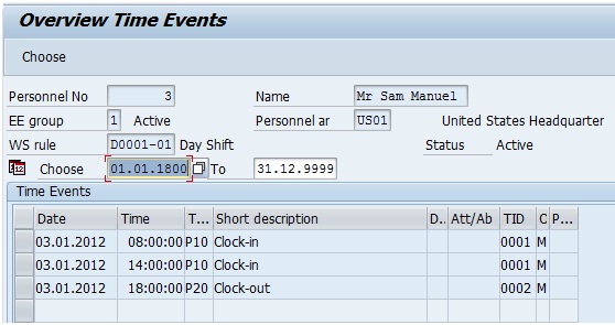
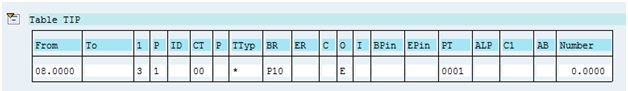
Please refer the below screenshot for time events in IT2011 to understand the shortcomings. The employee recorded a clock in at 08:00:00 and then clock outs at 10:30:00, 14:00:00 and 18:00:00 on 03-Jan-12.

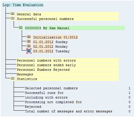
When the time evaluation is run, the time pairs formed get sorted as shown in the screenshot below:

SAP has sorted all the time pairs first by “From” and then by “To” in Table TIP. Hence, the PBEG of first time pair comes out to be blank and the PEND of the last time pair comes out to be 10.5000. However, the real time scenario demands that the first clock in should be 08.0000 and the last clock out should be 18.0000. Hence, this solution approach failed.
Solution Logic
I realized that I was not having clarity of thought on the logic to develop this solution and hence, the various attempts resulted in failure. Finally, I thought to myself that if I have to give this requirement to an ABAPer, what would be the requirement I would give to develop a program to find the first clock in and last clock out. Also, if the first clock in or last clock out was missing, the system would report that.
After some thinking, I came up with the below logic for ABAPer for determining the first clock in and last clock out:
- Find all the recorded clock ins for a shift from the time pairs formed in Table TIP from function P2011. Please note the word “recorded” which I have used. It means that I am trying to find earliest or latest recorded times from the time events that have actually got recorded at the time recording terminals.
- Out of the recorded clock ins, find the earliest recorded clock in and latest recorded clock in.
- Find all the recorded clock outs for the shift from the time pairs formed in Table TIP from function P2011.
- Out of this recorded clock outs, find the earliest recorded clock out and latest recorded clock out.
- Then compare the earliest recorded clock in with earliest recorded clock out. If the earliest recorded clock in is less than the earliest recorded clock out, then the earliest recorded clock in is the first clock in of the shift and should be called P10. If the earliest recorded clock in is greater than the earliest recorded clock out, then there is a missing clock in. Hence, the first clock in of the shift should be blank.
- Then compare the latest recorded clock out with the latest recorded clock in. If the latest recorded clock out is greater than the latest recorded clock in, then the latest recorded clock out is the last clock out of the shift and should be called P20. If the latest recorded clock out is less than the latest recorded clock in, then there is a missing clock out. Hence, the last clock out of the shift should be blank.
Let us now test this logic to the time events in our failed solution approach. Below table shows the time pairs formed in Table TIP from function P2011.

Earliest Recorded Clock In = 08.0000
Latest Recorded Clock In = 08.0000
Earliest Recorded Clock Out = 10.5000
Latest Recorded Clock Out = 18.0000
We see that the “earliest recorded clock in” (08.0000) is less than the “earliest recorded clock out” (10.5000) and hence, the “earliest recorded clock in” is the first clock in of the shift. This is correct.
The “latest recorded clock out” (18.0000) is greater than the “latest recorded clock in” (08.0000) and hence, the “latest recorded clock out” is the last clock out of the shift. This is correct too.
Hence, the above solution logic proved correct and I built custom PCRs and time types to fulfill the requirement based on this logic.
Solution Design
There are two key tables which we would need to maintain to build this solution.
- TPT_PAIRSTAT2 - Pair Formation: Status Table
- V_T705B - PDC Processing Statuses
Table TPT_PAIRSTAT2 determines how time pairs are formed in Table TIP.
Below is a partial screenshot of the Pair Formation Status Table.

From State: At any time, an employee has a state. This is the state in which the employee is in before the time event happens.
Time Event Type: The field shows the time event recorded when the employee is in a given state. It will change the state of the employee from “From state” to “To State”.
Unique Time Event Type: Time Event Type P01 can be used to record both clock in/clock out. If the “From state” of employee is absent before clock in and the “Time Event Type” is P01, then it means that the employee has clocked in. In such a case, the value of “Unique time event type” will be P10. This interpretation is defined in this field. Where no unique interpretation is required, the value of time event type is same as unique time event type. As shown in the screenshot above, the value of both time event type and unique time event type are P10 for “From state” – Absent before Clock In because no unique interpretation is needed.
To State: This is the state at which employee reaches from “From State” once the time event type is recorded.
Continue: This field is used for interim postings. Let us say that there is an interim posting between clock out and clock in and we would like to have two complete pairs – one from clock out to interim posting and another from interim posting to clock in. The first two events form the first time pair and the third event ends the new time pair taking the end event of previous time pair as the start event of the new time pair.
Closed: Time pairs are formed by a starting time event and an ending time event. However, if a time event is missing, then the pair won’t get formed or if there are multiple time events, incorrect time pairs may be formed. To avoid any errors, this check box should be checked for scenarios where the time event type is the ending time event and there is a missing starting time event type. This implies that the time event should create a new closed time pair only with “To” time and the “From” time will be blank. An example of this scenario is where clock in is missing and clock out is recorded.
Close: This field is meant to close an open time pair if it exists. If the employee is at work and a time event is recorded and this field is checked, then the pair should be closed. Fields Close and Closed are mutually exclusive. Both of them can’t be maintained at the same time for the same states and time event type.
New: This field means that a new time pair should be started.
Customer Adjustment: This field is used to specify PDC Processing Status and its reaction maintained in Table V_T705B.
Error: If the pair formation is not error free, it gives an error message in time evaluation run corresponding to the error message number maintained here.
Pair Formation Status: This field gives the status of the time pair formed – whether it is error free or not or clock in is missing or clock out is missing etc.
Let us now understand the PDC Processing Statuses Table V_T705B.
This table specifies the actions to be taken in situations where time pairs can’t be formed because the time events data don’t make sense.

PSGrp: This is Grouping of Personnel Subareas for Time Recording for which the same time types, time transfer specifications, access control groups, and message types are defined.
PDC Processing Status: This field displays the PDC Processing Status which defines the behavior to be taken into account during time pair formation.
Processing Status Text: This field displays the description of the PDC Processing Status.
Start Date: This field displays the start date from which the PDC Processing Status is valid.
End Date: This field displays the end date till which the PDC Processing Status is valid.
Reaction: The return code in field reaction will specify the reactions to be taken for PDC Processing Status.
Let us now study the values relevant for our scenarios from Pair Formation Status Table and the relevant values (C02 & C11) from PDC Processing Statuses Table.
TPT_PAIRSTAT2 Screenshot A – This shows the values in the table relevant for our scenarios.

V_T705B Screenshot B – The highlighted rows in the table show the values relevant for our scenarios.

Let us refer to the 2nd and 6th rows in Table TPT_PAIRSTAT2 Screenshot A. In both cases, employee was not at work and there was a clock out recorded. The system has to create a time pair with the clock out time event because the field “Closed” is checked. The “Customer adjustment” field has PDC Processing Status as C02 and the error message 21 (Clock in Missing) will get generated. The reaction field in Table V_T705B Screenshot B for PDC Processing Status C02 should be left blank to allow open time pair creation with only clock out time in Table TIP from function P2011. The time pair will have “From” field blank and “To” field with clock out time.
The other possible reaction value for PDC Processing Status C02 is 1. If 1 is maintained, then it doesn’t allow even creation of open time pair with just clock out data.
Below are the examples of system behavior with reaction as blank and as 1 for PDC Processing Status C02.
PDC Processing Status Scenario 1: Reaction indicator is blank for PDC Processing Status C02.
V_T705B

IT2011

P2011 – Open Pair Type gets created with clock out data and clock in is missing.

Time Evaluation Result – The time evaluation fails with error that clock in is missing.

PDC Processing Status Scenario 2: Reaction indicator is 1 for PDC Processing Status C02.
V_T705B

IT2011

Time Evaluation Result – The time evaluation fails at PCR TD20 which points out that time pair is not error free and has clock in missing. It doesn’t allow the system to reach function P2011 which creates open time pair with clock out time. Hence, this option is ruled out.

Let us refer to the 3rd row in Table TPT_PAIRSTAT2 Screenshot A. The employee was at work and a clock in was recorded. The field “Close” is checked and hence, it will close the open pair. Also, the field “New” is checked and hence, it will start the creation of a new time pair. The PDC Processing Status in field “Customer Adjustment” is C11. The reaction indicator for PDC Processing Status C11 is 1. If the reaction is 1, the system will end ongoing time pair with the current clock in time and also start a new time pair with the same clock in time. If the reaction for PDC Processing Status is blank, the system will give an error that clock in is missing.
PDC Processing Status Scenario 3: Reaction indicator is 1 for PDC Processing Status C11.
V_T705B

IT2011 – Employee is at work (Clock In 08:00:00) and clocks in again (14:00:00). It means that there is a missing clock out between two clock ins.
P2011 – There wasn’t any clock out at 14.0000. However, the system closes the existing open pair with the clock in time and starts a new time pair with the same clock in time. This is due to PDC Processing Status C11 and its return code as 1.

Time Evaluation Result – The time evaluation run is successful.
PDC Processing Status Scenario 4: Reaction indicator is blank for PDC Processing Status C11.
V_T705B

IT2011 – Employee is at work (Clock In 08:00:00) and clocks in again (14:00:00). It means that there is a missing clock out between two clock ins.

Time Evaluation Result – The time evaluation fails at PCR TD20 and generates error during pair formation. It doesn’t allow system to reach function P2011 for processing. Hence, this option is ruled out.

After maintaining Pair Formation Status Table - TPT_PAIRSTAT2 and PDC Processing Statuses Table - V_T705B, the next step is to create time types. Below are the daily time types which are needed.
- Earliest Recorded Clock In – ZVB1
- Latest Recorded Clock In – ZVB2
- Earliest Recorded Clock Out – ZVB3
- Latest Recorded Clock Out – ZVB4
- First Clock In – ZVB5
- Last Clock Out – ZVB6
Go to TCode SM30 > Table V_T555A.
ZVB1 – Earliest Recorded Clock In

ZVB2 – Latest Recorded Clock In

ZVB3 – Earliest Recorded Clock Out
ZVB4 – Latest Recorded Clock Out

ZVB5 – First Clock In

ZVB6 – Last Clock Out

After creating the six daily time types, I created five PCRs as mentioned below:
- ZVB4 - Find Earliest Recorded Clock In and Latest Recorded Clock In
- ZVB5 - Find Earliest Recorded Clock Out and Latest Recorded Clock Out
- ZVB6 - Determine First Clock In
- ZVB7 - Determine Last Clock Out
- ZVB9 - Form Time Pair in TIP using First Clock In & Last Clock Out
Let us now go inside each PCR to understand its functionality.
PCR ZVB4 – The objective of PCR ZVB4 is to find the “earliest recorded clock in” and “latest recorded clock in” in a shift and feed the values in daily time types ZVB1 (earliest recorded clock in) and ZVB2 (latest recorded clock in).
If no clock in has been recorded, then the daily time types ZVB1 and ZVB2 won’t get generated. If only one clock in has been recorded, then both ZVB1 and ZVB2 will have the same value.
Below is a screenshot of PCR ZVB4.

Let us see how time pairs in TIP table get processed through PCR ZVB4.
- The PCR checks if start time exists in time pair or not using OUTTPEXBTM. If start time doesn’t exist (N), the time pair is moved to output table using COLOP *. If all time pairs of the shift don’t have start time, then time typesZVB1 and ZVB2 aren’t created. Hence, the values of ZVB1 and ZVB2 are 0.
- If the start time exists (Y) in time pair, the value of time type ZVB1 (Earliest Recorded Clock In) is read using HRS=DZVB1. If it is the first time pair with start time and getting processed in the rule, the value of ZVB1 will be 0. If it is not the first time pair with start time, then there will be some value in time type ZVB1.
- After reading the value of time type ZVB1, it is compared with 0 using HRS?0. If the value of ZVB1 is not greater than 0, it is processed under * and the start time of the time pair is read using HRS=PBEG. The start time is added to time types ZVB1 (earliest recorded clock in) and ZVB2 (latest recorded clock in) and the time pair is moved to output table using COLOP *.
- Let us assume that the first time pair with start time had start time as 10:00:00. Hence, the value of ZVB1 and ZVB2 will be 10.0000. Now let us assume that the next time pair with start time has start time as 08:00:00. This time pair will get processed through Y (OUTTPEXBTM). The value of time type ZVB1 is read using HRS=DZVB1 (ZVB1 = 10.0000). This value is compared with 0 using HRS?0 and since the value of ZVB1 (10.0000) is greater than 0, the time pair gets processed under >. Then the start time of the time pair is read using HRS=PBEG (HRS = 08.0000) and it is compared with “earliest recorded clock in” time type ZVB1 (10.0000) using HRS?DZVB1. Since the value of HRS=PBEB (08.0000) is not greater than ZVB1 (10.0000), the start time of this time pair is the new “earliest recorded clock in” for this shift and gets processed under *. Hence, the start time (08.0000) of the current time pair is fed into daily time type ZVB1 after removing its old value 10.0000 using ADDDBZVB1Z and the time pair is moved to output table using COLOP *.
- Currently, the value of ZVB1 and ZVB2 are 08.0000 and 10.0000 respectively. Let us assume now that the next time pair with start time has start time as 15:00:00. This time pair will get processed through Y (OUTTPEXBTM). The value of time type ZVB1 is read using HRS=DZVB1 (ZVB1 = 08.0000). This value is compared with 0 using HRS?0 and since the value of ZVB1 (08.0000) is greater than 0, the time pair gets processed under >. Then the start time of the time pair is read using HRS=PBEG (HRS = 15.0000) and it is compared with “earliest recorded clock in” time type ZVB1 (08.0000) using HRS?DZVB1. Since the value of HRS=PBEG (15.0000) is greater than “earliest recorded clock in” time type ZVB1 (08.0000), the time pair gets processed under >. Then the value of HRS=PBEG (15.0000) is compared with “latest recorded clock in” time type ZVB2 (10.0000). Since the value of HRS=PBEB (15.0000) is greater than ZVB2 (10.0000), the start time of this time pair is the new “latest recorded clock in” for this shift and it gets processed under >. Hence, the start time (15.0000) of the current time pair is fed into daily time type ZVB2 after removing its old value 10.0000 using ADDDBZVB2Z and the time pair is moved to output table using COLOP *.
- Currently, the value of ZVB1 and ZVB2 are 08.0000 and 15.0000 respectively. Let us assume now that the next time pair with start time has start time as 13:00:00. This time pair will get processed through Y (OUTTPEXBTM). The value of time type ZVB1 is read using HRS=DZVB1 (ZVB1 = 08.0000). This value is compared with 0 using HRS?0 and since the value of ZVB1 (08.0000) is greater than 0, the time pair gets processed under >. Then the start time of the time pair is read using HRS=PBEG (HRS = 13.0000) and it is compared with “earliest recorded clock in” time type ZVB1 (08.0000) using HRS?DZVB1. Since the value of HRS=PBEG (13.0000) is greater than “earliest recorded clock in” time type ZVB1 (08.0000), the time pair gets processed under >. Then the value of HRS=PBEG (13.0000) is compared with “latest recorded clock in” time type ZVB2 (15.0000). Since the value of HRS=PBEB (13.0000) is not greater than ZVB2 (15.0000), the start time of this time pair is not the new “latest recorded clock in” for this shift and it gets processed under *. Hence, this time pair is moved into output table using COLOP *.
- Finally, the value of “earliest recorded clock in” time type ZVB1 and “latest recorded clock in” time type ZVB2 are 08.0000 and 15.0000 respectively.
PCR ZVB5 – The objective of PCR ZVB5 is to find the “earliest recorded clock out” and “latest recorded clock out” in a shift and feed the values into daily time types ZVB3 (earliest recorded clock out) and ZVB4 (latest recorded clock out).
If no clock out has been recorded, then the daily time types ZVB3 and ZVB4 won’t get generated. If only one clock out has been recorded, then both ZVB3 and ZVB4 will have the same value.
Below is a screenshot of PCR ZVB5.

Let us see how time pairs in TIP table get processed through PCR ZVB5.
- The PCR checks if end time exists in time pair or not using OUTTPEXETM. If end time doesn’t exist (N), the time pair is moved to output table using COLOP *. If all time pairs of the shift don’t have end time, then time types ZVB3 and ZVB4 aren’t created. Hence, the values of ZVB3 and ZVB4 are 0.
- If the end time exists (Y) in time pair, the value of time type ZVB3 (Earliest Recorded Clock Out) is read using HRS=DZVB3. If it is the first time pair with end time and getting processed in the rule, the value of ZVB3 will be 0. If it is not the first time pair with end time, then there will be some value in time type ZVB3.
- After reading the value of time type ZVB3, it is compared with 0 using HRS?0. If the value of ZVB3 is not greater than 0, then the time pair gets processed under * and the end time of the time pair is read using HRS=PEND. The end time is added to time types ZVB3 (earliest recorded clock out) and ZVB4 (latest recorded clock out) and the time pair is moved to output table using COLOP *.
- Let us assume that the first time pair with end time had end time as 12:00:00. Hence, the value of ZVB3 and ZVB4 will be 12.0000. Now let us assume that the next time pair with end time has end time as 10:00:00. This time pair will get processed through Y (OUTTPEXETM). The value of time type ZVB3 is read using HRS=DZVB3 (ZVB3 = 12.0000). This value is compared with 0 using HRS?0 and since the value of ZVB3 (12.0000) is greater than 0, the time pair gets processed under >. Then the end time of the time pair is read using HRS=PEND (HRS = 10.0000) and it is compared with “earliest recorded clock out” time type ZVB3 (12.0000) using HRS?DZVB3. Since the value of HRS=PEND (10.0000) is not greater than ZVB3 (12.0000), the end time of this time pair is the new “earliest recorded clock out” for this shift and it gets processed under *. Hence, the end time (10.0000) of the current time pair is fed into daily time type ZVB3 after removing its old value 12.0000 using ADDDBZVB3Z and the time pair is moved to output table using COLOP *.
- Currently, the value of ZVB3 and ZVB4 are 10.0000 and 12.0000 respectively. Let us assume now that the next time pair with end time has end time as 18:00:00. This time pair will get processed through Y (OUTTPEXETM). The value of time type ZVB3 is read using HRS=DZVB3 (ZVB3 = 10.0000). This value is compared with 0 using HRS?0 and since the value of ZVB3 (10.0000) is greater than 0, the time pair gets processed under >. Then the end time of the time pair is read using HRS=PEND (HRS = 18.0000) and it is compared with “earliest recorded clock out” time type ZVB3 (10.0000) using HRS?DZVB3. Since the value of HRS=PEND (18.0000) is greater than “earliest recorded clock out” time type ZVB3 (10.0000), the time pair gets processed under >. Then the value of HRS=PEND (18.0000) is compared with “latest recorded clock out” time type ZVB4 (12.0000). Since the value of HRS=PEND (18.0000) is greater than ZVB4 (12.0000), the end time of this time pair is the new “latest recorded clock out” for this shift and the time pair is processed under *. Hence, the end time (18.0000) of the current time pair is fed into daily time type ZVB4 after removing its old value 12.0000 using ADDDBZVB4Z and the time pair is moved to output table using COLOP *.
- Currently, the value of ZVB3 and ZVB4 are 10.0000 and 18.0000 respectively. Let us assume now that the next time pair with end time has end time as 16:00:00. This time pair will get processed through Y (OUTTPEXETM). The value of time type ZVB3 is read using HRS=DZVB3 (ZVB1 = 10.0000). This value is compared with 0 using HRS?0 and since the value of ZVB3 (10.0000) is greater than 0, the time pair gets processed under >. Then the start time of the time pair is read using HRS=PEND (HRS = 16.0000) and it is compared with “earliest recorded clock out” time type ZVB3 (10.0000) using HRS?DZVB3. Since the value of HRS=PEND (16.0000) is greater than “earliest recorded clock out” time type ZVB3 (10.0000), the time pair gets processed under >. Then the value of HRS=PEND (16.0000) is compared with “latest recorded clock out” time type ZVB4 (18.0000). Since the value of HRS=PEND (16.0000) is less than ZVB4 (18.0000), the end time of this time pair is not the new “latest recorded clock out” for this shift and the time pair gets processed under <. Hence, this time pair is moved into output table using COLOP *.
- Finally, the value of “earliest recorded clock out” time type ZVB3 and “latest recorded clock out” time type ZVB4 are 10.0000 and 18.0000 respectively.
PCR ZVB6 – The objective of PCR ZVB6 is to find the “first clock in” by comparing “earliest clock in” time type ZVB1 with “earliest clock out” time type ZVB3. If the value of ZVB1 is less than ZVB3, then ZVB1 is the “first clock in” and its value should be fed in time type ZVB5 – First Clock In.
If the value of ZVB1 is more than ZVB3, then there is a “missing clock in”. The “missing clock in” is the “first clock in” and hence, the value of ZVB5 will be 0.0000.
If ZVB1 was not created due to “missing clock in”, then the value of ZVB5 will be 0.0000 implying that there is a “missing clock in”.
Below is a screenshot of PCR ZVB6.

- Scenario 1: “Earliest Recorded Clock In” Time Type ZVB1 not created and “Earliest Recorded Clock Out” Time Type ZVB3 has value 10.0000 - The PCR ZVB6 reads the value of “earliest recorded clock in” time type ZVB1 (blank) using HRS=DZVB1 and then subtracts the value of “earliest recorded clock out” time type ZVB3 (10.0000) using HRS-DZVB3. The result is compared with 0 using HRS?0 and since this is not greater than 0, it gets processed under *. The value of “earliest recorded clock in” time type ZVB1 is read using HRS=DZVB1 and is fed into “first clock in” time type ZVB5 using ADDDBZVB5Z. The value of ZVB5 is 0.0000 implying that the “first clock in” is missing.
- Scenario 2: “Earliest Recorded Clock In” Time Type ZVB1 has value 08.0000 and “Earliest Recorded Clock Out” Time Type ZVB3 has value 10.0000 - The PCR ZVB6 reads the value of “earliest recorded clock in” time type ZVB1 (08.0000) using HRS=DZVB1 and then subtracts the value of “earliest recorded clock out” time type ZVB3 (10.0000) using HRS-DZVB3. The result is compared with 0 using HRS?0 and since this is not greater than 0, it gets processed under *. The value of “earliest recorded clock in” time type ZVB1 (08.0000) is read using HRS=DZVB1 and is fed into “first clock in” time type ZVB5 using ADDDBZVB5Z. Hence, the value of ZVB5 is 08.0000.
- Scenario 3: “Earliest Recorded Clock In” Time Type ZVB1 has value 12.0000 and “Earliest Recorded Clock Out” Time Type ZVB3 has value 10.0000 - The PCR ZVB6 reads the value of “earliest recorded clock in” time type ZVB1 (12.0000) using HRS=DZVB1 and then subtracts the value of “earliest recorded clock out” time type ZVB3 (10.0000) using HRS-DZVB3. The result is compared with 0 using HRS?0 and since this is greater than 0, it gets processed under >. The result is compared with “earliest recorded clock in” time type ZVB1 (12.0000) using operation HRS?DZVB1 and since the result is less than the value of ZVB1, it gets processed under <. Using HRS=0.00, the value is set to 0 and then fed into “first clock in” time type ZVB5 using ADDDBZVB5Z. Hence, the value of ZVB5 is 0.0000 implying that the “first clock in” is missing.
- Scenario 4: “Earliest Recorded Clock In” Time Type ZVB1 has value 08.0000 and “Earliest Recorded Clock Out” Time Type ZVB3 has value 0.0000 - The PCR ZVB6 reads the value of “earliest recorded clock in” time type ZVB1 (08.0000) using HRS=DZVB1 and then subtracts the value of “earliest recorded clock out” time type ZVB3 (0.0000) using HRS-DZVB3. The result is compared with 0 using HRS?0 and since this is greater than 0, it gets processed under >. The result is compared with “earliest recorded clock in” time type ZVB1 (08.0000) using operation HRS?DZVB1 and since the result is equal to the value of ZVB1, it gets processed under =. The value of “earliest recorded clock in” time type ZVB1 (08.0000) is read using HRS=DZVB1 and then fed into “first clock in” time type ZVB5 using ADDDBZVB5Z. Hence, the value of ZVB5 is 08.0000.
PCR ZVB7 – The objective of PCR ZVB7 is to find the “last clock out” by comparing “latest clock out” time type ZVB4 with “latest clock in” time type ZVB2. If the value of ZVB4 is greater than ZVB2, then ZVB4 is the “last clock out” and its value should be fed in time type ZVB6 – Last Clock Out.
If the value of ZVB4 is less than ZVB2, then there is a “missing clock out”. The “missing clock out” is the “last clock out” and hence, the value of ZVB6 will be 0.0000.
If ZVB4 was not created due to “missing clock out”, then the value of ZVB6 will be 0.0000 implying that there is a “missing clock out”.
Below is a screenshot of PCR ZVB7.

- Scenario 1: “Latest Recorded Clock Out” Time Type ZVB4 not created and “Latest Recorded Clock In” Time Type ZVB2 has value 12.0000 - The PCR ZVB7 reads the value of “latest recorded clock out” time type ZVB4 (blank) using HRS=DZVB4 and then subtracts the value of “latest recorded clock in” time type ZVB2 (12.0000) using HRS-DZVB2. The result is compared with 0 using HRS?0 and since this is not greater than 0, it gets processed under *. Using HRS=0.00, the value is set to 0 and then fed into “last clock out” time type ZVB6 using ADDDBZVB6Z. Hence, the value of ZVB6 is 0.0000 implying that the “last clock out” is missing.
- Scenario 2: “Latest Recorded Clock Out” Time Type ZVB4 has value 18.0000 and “Latest Recorded Clock In” Time Type ZVB2 has value 12.0000 - The PCR ZVB7 reads the value of “latest recorded clock out” time type ZVB4 (18.0000) using HRS=DZVB4 and then subtracts the value of “latest recorded clock in” time type ZVB2 (12.0000) using HRS-DZVB2. The result is compared with 0 using HRS?0 and since this is greater than 0, it gets processed under >. The value of “latest recorded clock out” time type ZVB4 (18.0000) is read using HRS=DZVB4 and then fed into “last clock out” time type ZVB6 using ADDDBZVB6Z. Hence, the value of ZVB6 is 18.0000.
- Scenario 3: “Latest Recorded Clock Out” Time Type ZVB4 has value 14.0000 and “Latest Recorded Clock In” Time Type ZVB2 has value 16.0000 - The PCR ZVB7 reads the value of “latest recorded clock out” time type ZVB4 (14.0000) using HRS=DZVB4 and then subtracts the value of “latest recorded clock in” time type ZVB2 (16.0000) using HRS-DZVB2. The result is compared with 0 using HRS?0 and since this is not greater than 0, it gets processed under *. Using HRS=0.00, the value is set to 0 and then fed into “last clock out” time type ZVB6 using ADDDBZVB6Z. Hence, the value of ZVB6 is 0.0000 implying that the “last clock out” is missing.
- Scenario 4: “Latest Recorded Clock Out” Time Type ZVB4 has value 18.0000 and “Latest Recorded Clock In” Time Type ZVB2 not created - The PCR ZVB7 reads the value of “latest recorded clock out” time type ZVB4 (18.0000) using HRS=DZVB4 and then subtracts the value of “latest recorded clock in” time type ZVB2 (0.0000) using HRS-DZVB2. The result is compared with 0 using HRS?0 and since this is greater than 0, it gets processed under >. The value of “latest recorded clock out” time type ZVB4 (18.0000) is read using HRS=DZVB4 and then fed into “last clock out” time type ZVB6 using ADDDBZVB6Z. Hence, the value of ZVB6 is 18.0000.
By now, we have identified the “first clock in” and “last clock out” of a shift. We also have the solution logic in place to identify if the “first clock in” or “last clock out” of any shift is missing or not.
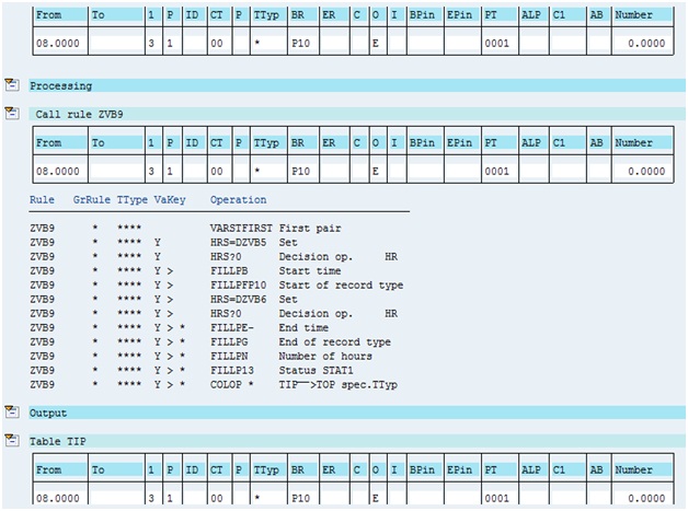
PCR ZVB9 - The next step is to create a time pair using the “first clock in” and “last clock out” that we have determined and process only this time pair for further evaluation. Any other time pair if present gets eliminated from further processing.
Below is the screenshot of PCR ZVB9.

The PCR ZVB9 uses VARSTFIRST to read the first time pair. If it is the first time pair, it gets processed under Y. Any other time pair gets stopped at N and doesn’t move to output table. In this way, we are ensuring that only one time pair will move to output table for further processing.
The first time pair will be modified with the “first clock in” and “last clock out” data and will be moved to output for further processing.
Below are the four possible scenarios that may happen.
Scenario 1: Both “First Clock In” (ZVB5) and “Last Clock Out” (ZVB6) have value as 0.0000 – The first time pair moves for processing under Y. The value of “first clock in” time type ZVB5 (0.0000) is read using HRS=DZVB5 and then compared with 0 using HRS?0. Since the result is not greater than 0, the processing happens under *. Below things happen for the first time pair:
- The start time of the time pair is deleted using FILLPB-
- The start of record type (P10) is deleted using FILLPF
- The no. of hours is reduced to 0.0000 using FILLPN
Then the value of the “last clock out” time type ZVB6 (0.0000) is read using HRS=DZVB6 and then compared with 0 using HRS?0. Since the result is not greater than 0, the processing happens under *. Below things happen for the first time pair:
- The end time of the time pair is deleted using FILLPE-
- The end of record type (P20) is deleted using FILLPG
- The status of the time pair is changed to 1 using FILLP11 implying that both start and end times are missing from the time pair
- The time pair is moved to output table for further processing using COLOP *.
- Hence, the time pair has both “From” time and “To” time as blank.
Scenario 2: “First Clock In” (ZVB5) and “Last Clock Out” (ZVB6) have value as 0.0000 and 18.0000 respectively – The first time pair moves for processing under Y. The value of “first clock in” time type ZVB5 (0.0000) is read using HRS=DZVB5 and then compared with 0 using HRS?0. Since the result is not greater than 0, the processing happens under *. Below things happen for the first time pair:
- The start time of the time pair is deleted using FILLPB-
- The start of record type (P10) is deleted using FILLPF
- The no. of hours is reduced to 0.0000 using FILLPN
Then the value of the “last clock out” time type ZVB6 (18.0000) is read using HRS=DZVB6 and then compared with 0 using HRS?0. Since the result is greater than 0, the processing happens under >. Below things happen for the first time pair:
- The end time of the time pair is filled with value of “last clock out” time type ZVB6 (18.0000) using FILLPE.
- The end of record type (P20) is added to time pair using FILLPG
- The status of the time pair is changed to 2 using FILLP12 implying that clock in time is missing from time pair.
- The time pair is moved to output table for further processing using COLOP *.
- Hence, the time pair has “From” time and “To” time as blank and 18.0000 respectively.
Scenario 3: “First Clock In” (ZVB5) and “Last Clock Out” (ZVB6) have value as 08.0000 and 0.0000 respectively – The first time pair moves for processing under Y. The value of “first clock in” time type ZVB5 (08.0000) is read using HRS=DZVB5 and then compared with 0 using HRS?0. Since the result is greater than 0, the processing happens under >. Below things happen for the first time pair:
- The start time of the time pair is set from “first clock in” time type ZVB5 using FILLPB.
- The start of record type (P10) is set for time pair using FILLPFP10.
Then the value of the “last clock out” time type ZVB6 (0.0000) is read using HRS=DZVB6 and then compared with 0 using HRS?0. Since the result is not greater than 0, the processing happens under *. Below things happen for the first time pair:
- The end time of the time pair is deleted using FILLPE-
- The end of record type (P20) is deleted using FILLPG
- The no. of hours is reduced to 0.0000 using FILLPN
- The status of the time pair is changed to 3 using FILLP13 implying that clock out time is missing from time pair.
- The time pair is moved to output table for further processing using COLOP *.
- Hence, the time pair has “From” time and “To” time as 08.0000 and blank respectively.
Scenario 4: “First Clock In” (ZVB5) and “Last Clock Out” (ZVB6) have value as 08.0000 and 18.0000 – The first time pair moves for processing under Y. The value of “first clock in” time type ZVB5 (08.0000) is read using HRS=DZVB5 and then compared with 0 using HRS?0. Since the result is greater than 0, the processing happens under >. Below things happen for the first time pair:
- The start time of the time pair is set from “first clock in” time type ZVB5 using FILLPB.
- The start of record type (P10) is set for time pair using FILLPFP10.
Then the value of the “last clock out” time type ZVB6 (18.0000) is read using HRS=DZVB6 and then compared with 0 using HRS?0. Since the result is greater than 0, the processing happens under >. Below things happen for the first time pair:
- The end time of the time pair is set from “last clock out” time type ZVB6 (18.0000) using FILLPE.
- The end of record type (P20) is set for time pair using FILLPGP20.
- The status of the time pair is changed to 0 using FILLP10 implying that the pair is error free with both start time and end time.
- The time pair is moved to output table for further processing using COLOP *.
- Hence, the time pair has “From” time and “To” time as 08.0000 and 18.0000 respectively.
The next step is to include these PCRs ZVB4, ZVB5, ZVB6, ZVB7 and ZVB9 in positive time management schema.
A custom schema ZTCN is created by copying from standard time schema TM00 – Time Evaluation with Personnel Time Events.
Below is a screenshot of the custom time schema ZTCN.

The PCRs ZVB4, ZVB5, ZVB6, ZVB7 and ZVB9 are included in time schema ZTCN as per the sequence shown in the above screenshot.
PCRs ZVB4, ZVB5 and ZVB9 are being processed by function PTIP because TIP table is being processed in these PCRs. Par 2 is GEN because it is called for all time types.
PCRs ZVB6 and ZVB7 are being processed by function ACTIO because TIP table is not being processed in these PCRs.
I have included function PRINT after PCRs ZVB4 and ZVB5 to print table TES to display the value of time types ZVB1, ZVB2, ZVB3 and ZVB4 which get generated in these PCRs.
In the same way, I have included function PRINT after PCRs ZVB6 and ZVB7 to print table TES to display the value of time types ZVB5 and ZVB6 which get generated in these PCRs.
I tested around 22 different scenarios for this solution and all the scenarios passed with the desired result.
Please refer the below screenshots for the results.


I will now pick up some scenarios from the 22 scenarios that I tested and show how the time events got processed in system.
Testing Scenario 1:
IT2011

P2011

Table TES

Final Pair Formed
Time Evaluation Result – It fails since last clock out is missing.

Testing Scenario 2:
IT2011

P2011

Table TES

Final Pair Formed

Time Evaluation Result – It fails since first clock in is missing.

Testing Scenario 3:
IT2011

P2011

Table TES

Final Pair Formation
Time Evaluation Result – It fails since last clock out is missing

Testing Scenario 4:
IT2011

P2011

Table TES

Final Pair Formation

Time Evaluation Result – It is successful.

Here I come to the end of this knowledge artifact. Thank you for your patience for going through this document. I hope this knowledge artifact has been beneficial for you.
Warm regards,
Vivek Barnwal
**************************************************************************************************
You can also refer to other knowledge artifacts created by me at the below link:
One Stop Shop of my Knowledge Artifacts in SAP HCM
- SAP Managed Tags:
- HCM (Human Capital Management)
91 Comments
- « Previous
-
- 1
- 2
- Next »
You must be a registered user to add a comment. If you've already registered, sign in. Otherwise, register and sign in.
Labels in this area
-
"mm02"
1 -
A_PurchaseOrderItem additional fields
1 -
ABAP
1 -
ABAP Extensibility
1 -
ACCOSTRATE
1 -
ACDOCP
1 -
Adding your country in SPRO - Project Administration
1 -
Advance Return Management
1 -
AI and RPA in SAP Upgrades
1 -
Approval Workflows
1 -
ARM
1 -
ASN
1 -
Asset Management
1 -
Associations in CDS Views
1 -
auditlog
1 -
Authorization
1 -
Availability date
1 -
Azure Center for SAP Solutions
1 -
AzureSentinel
2 -
Bank
1 -
BAPI_SALESORDER_CREATEFROMDAT2
1 -
BRF+
1 -
BRFPLUS
1 -
Bundled Cloud Services
1 -
business participation
1 -
Business Processes
1 -
CAPM
1 -
Carbon
1 -
Cental Finance
1 -
CFIN
1 -
CFIN Document Splitting
1 -
Cloud ALM
1 -
Cloud Integration
1 -
condition contract management
1 -
Connection - The default connection string cannot be used.
1 -
Custom Table Creation
1 -
Customer Screen in Production Order
1 -
Data Quality Management
1 -
Date required
1 -
Decisions
1 -
desafios4hana
1 -
Developing with SAP Integration Suite
1 -
Direct Outbound Delivery
1 -
DMOVE2S4
1 -
EAM
1 -
EDI
2 -
EDI 850
1 -
EDI 856
1 -
edocument
1 -
EHS Product Structure
1 -
Emergency Access Management
1 -
Energy
1 -
EPC
1 -
Financial Operations
1 -
Find
1 -
FINSSKF
1 -
Fiori
1 -
Flexible Workflow
1 -
Gas
1 -
Gen AI enabled SAP Upgrades
1 -
General
1 -
generate_xlsx_file
1 -
Getting Started
1 -
HomogeneousDMO
1 -
IDOC
2 -
Integration
1 -
Learning Content
2 -
LogicApps
2 -
low touchproject
1 -
Maintenance
1 -
management
1 -
Material creation
1 -
Material Management
1 -
MD04
1 -
MD61
1 -
methodology
1 -
Microsoft
2 -
MicrosoftSentinel
2 -
Migration
1 -
MRP
1 -
MS Teams
2 -
MT940
1 -
Newcomer
1 -
Notifications
1 -
Oil
1 -
open connectors
1 -
Order Change Log
1 -
ORDERS
2 -
OSS Note 390635
1 -
outbound delivery
1 -
outsourcing
1 -
PCE
1 -
Permit to Work
1 -
PIR Consumption Mode
1 -
PIR's
1 -
PIRs
1 -
PIRs Consumption
1 -
PIRs Reduction
1 -
Plan Independent Requirement
1 -
Premium Plus
1 -
pricing
1 -
Primavera P6
1 -
Process Excellence
1 -
Process Management
1 -
Process Order Change Log
1 -
Process purchase requisitions
1 -
Product Information
1 -
Production Order Change Log
1 -
Purchase requisition
1 -
Purchasing Lead Time
1 -
Redwood for SAP Job execution Setup
1 -
RISE with SAP
1 -
RisewithSAP
1 -
Rizing
1 -
S4 Cost Center Planning
1 -
S4 HANA
1 -
S4HANA
3 -
Sales and Distribution
1 -
Sales Commission
1 -
sales order
1 -
SAP
2 -
SAP Best Practices
1 -
SAP Build
1 -
SAP Build apps
1 -
SAP Cloud ALM
1 -
SAP Data Quality Management
1 -
SAP Maintenance resource scheduling
2 -
SAP Note 390635
1 -
SAP S4HANA
2 -
SAP S4HANA Cloud private edition
1 -
SAP Upgrade Automation
1 -
SAP WCM
1 -
SAP Work Clearance Management
1 -
Schedule Agreement
1 -
SDM
1 -
security
2 -
Settlement Management
1 -
soar
2 -
SSIS
1 -
SU01
1 -
SUM2.0SP17
1 -
SUMDMO
1 -
Teams
2 -
User Administration
1 -
User Participation
1 -
Utilities
1 -
va01
1 -
vendor
1 -
vl01n
1 -
vl02n
1 -
WCM
1 -
X12 850
1 -
xlsx_file_abap
1 -
YTD|MTD|QTD in CDs views using Date Function
1
- « Previous
- Next »
Related Content
- Business Rule Framework Plus(BRF+) in Enterprise Resource Planning Blogs by Members
- SAP S/4HANA Cloud Public Edition 后勤常见热点问题汇总FAQ in Enterprise Resource Planning Blogs by SAP
- Product Compliance in SAP S/4HANA Cloud Public Edition 2402 in Enterprise Resource Planning Blogs by SAP
- Introduction into Advanced Foreign Currency Valuation in Enterprise Resource Planning Blogs by SAP
- VALUATION OF A MATERIALS BASED ON LIFO/FIFO METHODS in Enterprise Resource Planning Blogs by Members
Top kudoed authors
| User | Count |
|---|---|
| 6 | |
| 2 | |
| 2 | |
| 2 | |
| 2 | |
| 2 | |
| 2 | |
| 1 | |
| 1 | |
| 1 |