Introduction
When I initially started working on XI, I always wondered why an Integration scenarios and actions were provided in Design Time. I never knew why they were used for, because I never used them to execute a file-to-file scenario or in anyother advanced scenarios. Later when I tried to configure the demo examples using “SAP XI3.0: Demo examples” guide I realized the need for Scenario’s and actions. But by importing the existing Scenario’s from Design to Configuration hasn’t helped me much in understanding them. So I tried understanding these by creating a simple file-to-file scenario.
This weblog takes you through a hypothetical Business Case and helps you model an Integration Scenario for the same using SAP-XI. After completing this example you will appreciate modeling Integration Scenario’s in XI.
Scenario
BAN_PROD is software provided by ABC. VBU-Retail and VBU-Mfg are two business units of a Large Enterprise that use SAP-XI as middleware to exchange data between their systems. VBU- Mfg’s system (VBU_Retail_FS) sends out sends out Material details to VBU-Mfg’s System (VBU_Mfg_FS). BAN_PROD software has been installed on VBU_Retail_FS and VBU_Mfg_FS. This process is modeled using SAP-XI’s Integration Scenario.
Modeling in XI..?
Why is a model required..? To say it in simple terms…before u construct a house/ farm house, u like to have a prototype of it/ or say a model that gives you a rough idea of how exactly your farmhouse should look like. Where will your swimming pool be, and how big your lawn should be..? and what not…. Thinking on similar lines, an Integration Scenario completely models the exchange of messages in a Simple/Complex Business process.
It provides a bird’s view of the process flow and the message exchange between various systems and processes. It gives a clear picture of what are all the design time objects (Data types, Message Types, Message Interfaces etc. ). It also lists down the various Products versions used from the SLD. Above all, it acts as a template for the generation of Configuration Objects (Receiver Determination, Interface determination, Receiver agreements).
The bricks of an Integration scenario are Application Components, Actions and the cement being Connections between the actions. An application component represents a participant of an integration scenario. Actions are the functions provided by an application component and the flow of messages between the components is represented by connections between these actions.
Prerequisites
- In SLD, make a necessary entry for the Product BAN_PROD 1.0 of ABC and software component BAN_FILECOMP 1.0 component associated with it.

Fig.1 Product BAN_PROD 1.0 of ABC in SLD
- In SLD, make an entry for VBU_RETAIL_FS and VBU_MFG_FS as 3rd Party Applications with BAN_PROD of ABC as the associated Product in Technical Landscape.


Fig.2 VBU_MFG_FS System details from SLD
- In SLD, define VBU_RETAIL_FS and VBU_MFG_FS as Business systems for the corresponding Technical systems defined in Landscape.
- Import the VBU_Retail_FS and VBU_Mfg_FS business systems into configuration.
Sequence Of Steps
Design Time
- Create the Required Design Time Objects like Data Type, Message Type, Message Interfaces, Message Mapping and Interface Mapping.
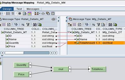
Fig.3 Design Time Objects.. MessageMapping
- Create a new Integration Scenario(Name: Retail_Mgr_Trading_Scenario) and Insert a new application component (VBU_Retail)
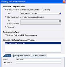
Fig.4 Applicaiton Component Detailsto be selected
- Create a new action (Type: internal, Name: Send_MaterialDetails) in VBU_Retail Application component.
- Similarly Create another Application component(VBU_MFG) and another action in the same component (Type: internal, Name : Receive_MateriaDetails).
- Go to Send_MaterialDetails action and specify the outbound Message Interface (Retail_Details_MI)

Fig.5 Specifying Actions Parameters
- Go to Receive_MaterialDetails action and specify the Inbound Message Interface (Mfg_Details_MI)
- In Integration Scenario, Select Send_MaterialDetails as start action(Right click on the action and mention it as start action)and Receive_MaterialDetails as End Action(Right click on the action and mention it as end action)
- Select the two actions( by pressing shift button) and create a new communication link between them. U will see the Inbound and outbound message interfaces. In the next tab, select the appropriate interface mapping

Fig.6 Integration Scenario Modelled during Design Time
- Save and active the Design Time Objects.
Configuration Time
- Create a sender communication channel(Name: VBU_Retail_FS, Type File, Fill in the other required parameters)
- Create a receiver Communication chanel(Name: VBU_MFG_FR, Type File, Fill in the other required parameters)
- Create a new Integration Scenario and choose the (Input help) and select the Integration Scenario that has been developed during the design time.

Fig.7 Integration Scenario Configurator wizard
- Save the Integration Scenario and click on Integration Scenario Configurator to open the editor.
- In the Editor, select the component view and apply it.
- In the Editor, Assign services. VBU_RETAIL to VBU_Retail_FS. Click on the „» arrow button and assign VBU_MFG to VBU_Mfg_FS.

Fig.8 Allocation of Systems to Applicaiton Components
- Configure your Connections. In the window select the Receiver Channel (MFG_Details_FR).
- U can check if the Actions, Interfaces and the Mappings are properly defined or not
- In the top level navigation, Generation„³ Check Configurability, check if there are any errors.
- In the generation tab, Check Generation, Permit changes buttons and start.
- On click of start u will see that a pop-up window comes up and the receiver determination, interface determination and receiver agreements are generated. U can look at the generated statistics in the file.

Fig.9 Configuration Time Objects being genertated
- Apply the changes and close the editor
- In configuration, u would have found the necessary objects have been generated.

Fig.10 Configuration Objects generated and added to Scenario
- The Sender agreement doesn't get created automatically. It should needs to be created manually.
- Save and activate the Configuration time objects.
Result
Place the file in the required folder of Source system and u will find that XI has processed the file and delivered it at the target location. Recommended Reading
Guidelines for Modeling Integration Scenarios U would have noticed that the Integration sccenario modelled in design time has been used as a template to generate the necessary configuration objects. I think you would have appreciated modeling of Integration Scenario’s in XI scenario. 